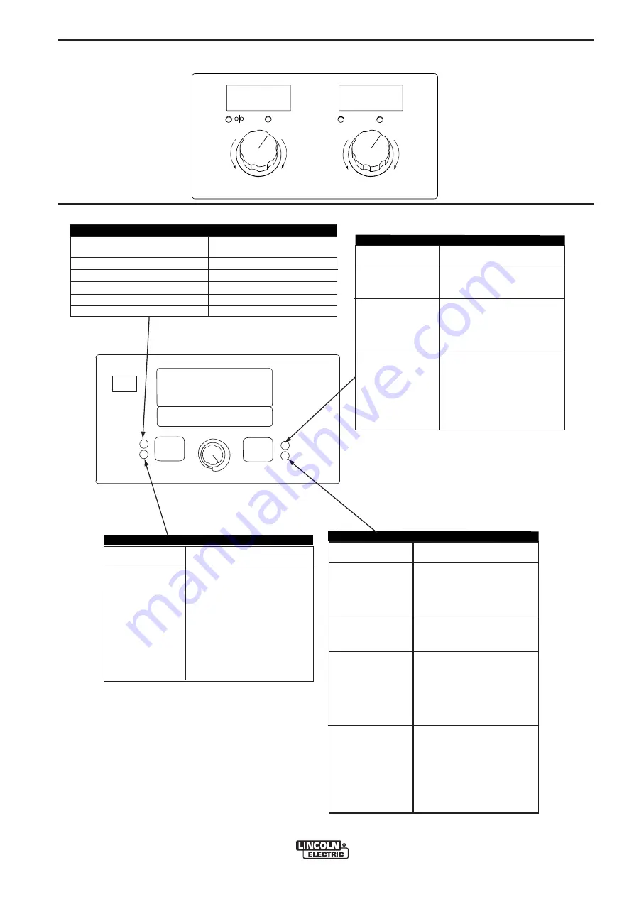
Lincoln Electric POWER FEED 10M Operator'S Manual Download Page 31

B-15

OPERATION

B-15

POWER FEED™ 25M

220

1.06

WFS      AMPS

VOLTS        TRIM

Less

Deposition

Shorter

Arc

Longer

Arc

More

Deposition

ARC 

FOCUS

-10.0 (SOFT to

10.0 (STIFF)

DESCRIPTION

Arc Focus adjusts the arc from

a wide, soft arc good for out of

position work to a narrow, stiff 

arc preferred for faster travel 

speeds. The pulse frequency is 

lower with a soft arc and higher

with a stiff arc. 

PREFLOW TIME

0 - 25.0 seconds

RUN-IN WFS:

Off, 30 to150 in/min.

Start Procedure

DESCRIPTION

Adjusts the time that shielding 

gas flows after  the  trigger is 

pulled and prior to feeding wire.

Run-in  sets  the  wire  feed

speed from the time the trigger

is pulled until an arc is estab-

lished.

The Start Procedure controls

the WFS, Trim at a specified

time at the beginning of the

weld. During the start time, the

machine will ramp up or down

from the Start Procedure to the

preset Welding Procedure.

EFFECT /  RANGE

Postflow Time:

0 to 25.0 seconds

Burnback: 0 to .25

Seconds

Crater Procedure

FUNCTION

Adjusts the time that shielding

gas flows after the welding out-

put turns off.

The  burnback  time  is  the

amount of time that the weld

output continues after the wire

stops feeding. It prevents the

wire from sticking in the puddle

and prepares the end of the

wire for the next arc start.

Crater Procedure controls the

WFS and Trim  for a specified

time at the end of the weld

after the trigger is released.

During the Crater time, the

machine will ramp up or down

from the Weld Procedure to

the Crater Procedure.

ELECTRODE AND

Steel(Crisp)

Steel(Soft)

Stainless

Stainless 

Stainless 

GAS

2

CO

2

CO

2

Ar(Mix)

Ar(Mix)

Ar/He/CO

Ar/

Ar/

WIRE SIZE

0.030   0.035   0.045   0.052 

---

14        19        28

95         12        22       201

66         36        46        ---

62         32        42        ---

---          34        44        ---

START OPTIONS

END OPTIONS

WELD MODE

ARC CONTROL

STEEL

.035"

SET

SETUP

IR PORT

Pulse Crisp ArMix

WAVEFORM CONTROL TECHNOLOGY

  WELD MODE
ARC CONTROL

12

START OPTIONS
END OPTIONS

Spot Timer 

0 to 120.0 Seconds

Adjust the time welding will

continue even if the trigger 

is still pulled. This option 

has no effect in 4-Step

Trigger Mode. 

MSP4  OPERATION

STEEL AND STAINLESS SYNERGIC GMAW-P (PULSED MIG) WELDING

All manuals and user guides at all-guides.com

all-guides.com

Summary of Contents for POWER FEED 10M

Page 1: ...Code Number 11313 11456 11557 11714 11715 Safety Depends on You Lincoln arc welding and cutting equipment is designed and built with safety in mind However your overall safety can be increased by prop...

Page 2: ...WITH THEIR DOCTOR BEFORE OPERATING Read and understand the following safety highlights For additional safety information it is strongly recommended that you purchase a copy of Safety in Welding Cutti...

Page 3: ...h electrically hot parts of electrode holders connected to two welders because voltage between the two can be the total of the open circuit voltage of both welders 3 i When working above floor level u...

Page 4: ...raulic lines Have a fire extinguisher readily available 6 b Where compressed gases are to be used at the job site special precautions should be used to prevent hazardous situations Refer to Safety in...

Page 5: ...mmables 4 Des gouttes de laitier en fusion sont mises de l arc de soudage Se prot ger avec des v tements de protection libres de l huile tels que les gants en cuir chemise paisse pan talons sans rever...

Page 6: ...he correct replacement parts On Line Product Registration Register your machine with Lincoln Electric either via fax or over the Internet For faxing Complete the form on the back of the warranty state...

Page 7: ...n B 36 thru B 38 Internal Controls B 39 B 40 Cold Feed Gas Purge Switch Light Switch Heater Switch Pressure Arm Adjustment B 41 2 Step 4 Step Trigger Operation and Graphics B 42 thru B 47 Rear Control...

Page 8: ...emory Panel Closed GEARING WIRE FEED SPEED RANGE WIRE SIZE PHYSICAL DIMENSIONS WFS RANGE 50 800 ipm 2 5 20 3m min 30 400 ipm 1 3 10 4m min WFS RANGE 50 800 ipm 2 5 20 3m min 30 400 ipm 1 3 10 4m min W...

Page 9: ...eeding performance place the POWER FEED 25M on a stable and dry surface Keep the wire feeder in a vertical position Do not operate the wire feeder on an angled surface of more than 15 degrees Do not s...

Page 10: ...ED 25M See 5 pin 6 pin and 7 pin Figure A 1 There is one circular connector on the rear of the POWER FEED 25M Maximum control cable length is 200 ft 61 m ARCLINK CONTROL CABLES See Figure A 3 ArcLink...

Page 11: ...ire feed er electrode connection 3 Connect the outer lead bundle to the power source work connection and the other end to the work piece Minimize the length of any work lead extension for best results...

Page 12: ...tlet fitting of the flow regulator Attach the other end to the welding system shielding gas inlet Tighten the union nuts with a wrench 6 Before opening the cylinder valve turn the regulator adjusting...

Page 13: ...t driver remove the five screws securing the wire drive panel Lift out the wire drive panel and disconnect the molex connections 11 Using a 5 16 nut driver remove the four screws secur ing the cover 1...

Page 14: ...thumb screw hole in the feed plate Slide the gun receiver bushing into the wire drive and verify the thumb screw holes are aligned 10 Tighten the socket head cap screw 11 Insert the welding gun into...

Page 15: ...d personnel should install use or service this equipment Loading 10 to 15 lb 4 5 6 8kg Spools A K468 spindle adapter is required for loading 2 51mm wide spools on 2 51mm spindles Use a K468 spindle ad...

Page 16: ...ts in maximum drive roll clamping pressure Patented split wire guides fully support the wire and virtually eliminate birdnesting No tools required to change the drive rolls and wire guides Patented du...

Page 17: ...umes Use ventilation or exhaust to remove fumes from breathing zone WELDING SPARKS can cause fire or explosion Keep flammable material away ARC RAYS can burn Wear eye ear and body protec tion SEE ADDI...

Page 18: ...num case with replaceable skids or an impact resistant polycarbonate plastic case The heart of the POWER FEED 25M is the MAXtrac drive The patented features on the wire drive offer tool less changing...

Page 19: ...is 50ft 15 2m for push pull systems Spool guns do not work with the POWER FEED 25M A remote control foot amptrol and a push pull gun may not be connected to the POWER FEED 25M simultaneously Maximum...

Page 20: ...hows detailed welding and diagnostic information 8 Left Button Changes the MSP4 display to show the Weld Mode or Arc Control 9 Right Button Changes the MSP4 display to show Start Options or End Option...

Page 21: ...Trigger connector for a push only gun 9 ON OFF switch Controls power to the POWER FEED 25M 10 6 pin connector Connector for a remote control 11 Cover Covers location for optional water cooling line 1...

Page 22: ...e LED will flash green and codes will repeat There may be more than one error code indicated To clear the error turn the power source OFF and then back ON to reset See Troubleshooting Section E STATUS...

Page 23: ...lit ed diam nonu mmy nibh euism od tincid unt ut laore et dolor e magn a aliqu am erat laore et dolor e magn a aliqu am erat Lorem ipsum dolor sit amet cons ectet uer adipi scing Lorem ipsum dolor sit...

Page 24: ...MP knob to adjust Start current while the Start Options LED is displayed No arc ending options are active for SMAW Stick welding modes PROCESS Stick Soft 7018 Stick Crisp 6010 MODE 1 2 CC STICK MODES...

Page 25: ...ld ed electrodes like Innershield POWER FEED 25M K2368 1 Power Wave 355M 1 K2202 1 Power Wave 455M K2203 1 Power Wave 455M STT K2230 1 POWER FEED 10M Bench Model K2234 1 POWER FEED 10M Dual Bench Mode...

Page 26: ...or the next arc start PROCESS GMAW STANDARD CV GMAW POWER MODE FCAW STANDARD CV WELD MODE 5 40 6 ARC CONTROL WELD MODE END OPTIONS START OPTIONS DESCRIPTION Pinch controls the arc characte ristics whe...

Page 27: ...K2368 1 Power Wave 355M 1 K2202 1 Power Wave 455M K2203 1 Power Wave 455M STT K2230 1 POWER FEED 10M Bench Model K2234 1 POWER FEED 10M Dual Bench Model K2536 1 2 3 POWER FEED 25M 2 KP1696 xx Drive R...

Page 28: ...ure to the preset Welding Procedure EFFECT RANGE Postflow Time 0 to 25 0 seconds Burnback 0 to 25 Seconds Crater Procedure DESCRIPTION Adjusts the time that shielding gas flows after the welding out p...

Page 29: ...e arc length and ranges from 0 50 to 1 50 Increasing the trim value increases the arc length while decreasing the trim value decreases the arc length FIGURE B 6 ARC CONTROL For steel and stainless pul...

Page 30: ...cons ecte tuer adip iscin g elit ed diam nonu mmy nibh euis mod tincid unt ut elit ed diam nonu mmy nibh euis mod tincid unt ut laore et dolo re mag na aliqu am erat laore et dolo re mag na aliqu am...

Page 31: ...sts the time that shielding gas flows after the welding out put turns off The burnback time is the amount of time that the weld output continues after the wire stops feeding It prevents the wire from...

Page 32: ...offers both traditional pulse and Pulse on Pulse Pulse on Pulse GMAW PP is an exclusive waveform for aluminum welding Use it to make welds with a stacked dime appearance similar to GTAW welds FIGURE B...

Page 33: ...l from the wire to the weld puddle Pulse welding controls the arc length with Trim instead of voltage When trim arc length is adjusted the Power Wave automatically recalculates the voltage current and...

Page 34: ...nsecte tuer adipiscin g Lorem ipsum dolor sit amet consecte tuer adipiscin g elit ed diam nonumm y nibh euismod tincidunt ut elit ed diam nonumm y nibh euismod tincidunt ut laoreet dolore magna aliqua...

Page 35: ...Procedure to the preset Welding Procedure EFFECT RANGE Postflow Time 0 to 25 0 seconds Burnback 0 to 25 Seconds Crater Procedure FUNCTION Adjusts the time that shielding gas flows after the welding o...

Page 36: ...he arc Synergic STT modes keep the arc characteristics the same when the wire feed speed is changed Note STT is available only with specially equipped Power Wave power sources like the Power Wave 455M...

Page 37: ...onds RUN IN WFS Off 30 to150 in min Start Procedure FUNCTION Adjusts the time that shielding gas flows after the trigger is pulled and prior to feeding wire Run in sets the wire feed speed from the ti...

Page 38: ...t into the weld Changing the background current changes the shape of the back bead 100 CO2 requires less background current than when welding with blended shielding gases FIGURE B 17 TAILOUT Tailout p...

Page 39: ...valves connect the output gas hose on the wire feeder to the TIG torch gas hose The wire feeder gas solenoid may be enabled or dis abled by parameter P 8 in the set up menu found in this operations s...

Page 40: ...magna aliquam erat laoreet dolore magna aliquam erat Lorem ipsum dolor sit amet consectetue r adipiscing Lorem ipsum dolor sit amet consectetue r adipiscing elit ed diam nonummy nibh euismod tincidun...

Page 41: ...The Setup Menu gives access to the Setup Configuration Stored in the setup configuration are user parameters that generally only need to be set at installation The parameters are grouped as shown in...

Page 42: ...is started or a user interface control is changed P 3 will only show up in the list if the power source is capable of calculating energy a power source software update may be necessary When P 3 No ene...

Page 43: ...any times as needed during the weld Release the trigger to stop weld ing The system will automatically return to procedure A settings Integral TrigProc When using a Magnum DS dual schedule gun or simi...

Page 44: ...tomatically while TIG welding Power source Solenoid Any gas solenoid connected to the power source will turn on and off automatically while TIG welding Notes Preflow is not available while TIG welding...

Page 45: ...tion and test purposes By default the machine does not include test weld modes in the list of weld modes that are available to the operator To manually select a test weld mode set this option to Yes W...

Page 46: ...ead the IP Address Press the left button to back out and exit this option The IP address cannot be changed using this option P 107 View Power Source Protocol Used for viewing the type of power source...

Page 47: ...nged from the Mode Select Panel all others Mode Select Panel settings are unlocked Wave Control Options Locked The Wave Control parameters on the Mode Select Panel are locked all others are unlocked S...

Page 48: ...e default weld mode and welding parame ters Presently this option does not exist in any setup menu P 509 UI Master Lockout Locks all user interface controls preventing the operator from making any cha...

Page 49: ...e is Disabled will appear briefly in the MSP4 display HOLD 2 SECONDS TO SAVE PROCEDURE MEMORY A GUN B 1 4 2 5 3 6 M M PROCEDURE MEMORY PANEL OPERA TION For Code 11313 The Dual Procedure Memory Panel p...

Page 50: ...mits are enabled the parameter will flash whenever an attempt is made to exceed the memory limit value The parameter will not flash if an attempt is made to exceed the machine limit Machine limits are...

Page 51: ...Name High Limit Low Limit The memory value must always be less than or equal to the high limit and greater than or equal to the low limit After setting limits press the memory button with the flashing...

Page 52: ...d the message Memory save is Disabled will appear briefly in the MSP4 display A GUN B 1 5 2 6 3 7 4 8 DUAL PROCEDURE MEMORY OPERATION For Code 11456 and Higher The Dual Procedure Memory buttons perfor...

Page 53: ...and wire feeder dependent Weld mode dependent 0 50 to 1 50 10 0 to 10 0 0 0 to 2 5 0 0 to 10 0 Off 50 to 150 0 0 to 10 0 0 00 to 0 25 0 0 to 10 0 Units in min Volts Weld mode dependent Seconds Second...

Page 54: ...00 Memory Value Parameter Name Low Limit High Limit The memory value must always be less than or equal to the high limit and greater than or equal to the low limit After setting limits press the memor...

Page 55: ...Switch 3 Wire Drive Pressure Arm 4 Internal Light Switch 5 Internal Heater Switch 6 Spindle Brake 7 Gun Bushing ITEM DESCRIPTION 1 9 8 7 6 3 2 8 Thumb Screw for securing the welding Gun 9 Socket Head...

Page 56: ...2 Wire Drive Pressure Arm 3 Internal Light Switch 4 Internal Heater Switch 5 Spindle Brake 6 Gun Bushing ITEM DESCRIPTION 1 8 7 6 3 2 7 Thumb Screw for securing the welding Gun 8 Socket Head Cap Screw...

Page 57: ...inside of the POWER FEED 25M The heater is useful for reduc ing condensation build up on the spool of wire The heater is thermo statically protected POWER FEED 25M COLD FEED GAS PURGE ON OFF LIGHT HEA...

Page 58: ...hoose the arc start weld and arc end time It may also be set up to work as a trigger inter lock 2 STEP 4 STEP 2 STEP 4 STEP TRIGGER OPERATION Code 11456 and higher The 2 Step 4 Step switch changes the...

Page 59: ...lished within 1 5 seconds the wire feed speed will jump to the welding wire feed speed WELD The power source output and the wire feed speed continue at the weld settings for as long as the trigger is...

Page 60: ...re touches the work and an arc is estab lished both the machine output and the wire feed speed ramp to the weld settings throughout the start time The time period of ramping from the start set tings t...

Page 61: ...er Released 2 Step Trigger Start ON Crater ON Burnback ON 1 5 secmax Start Starttime B urnback Time Downslope Crater Crater ti me Power Source Output Crater FIGURE B 21 EXAMPLE 3 2 STEP TRIGGER Custom...

Page 62: ...lled a second time and then released or if the arc is interrupted See Figure B 22 For this sequence PREFLOW Shielding gas begins to flow immediately when the gun trigger is pulled RUN IN After preflow...

Page 63: ...rigger is released UPSLOPE During upslope the power source output and the wire feed speed ramp to the weld settings throughout the start time The time period of ramping from the start settings to the...

Page 64: ...CONTROLS POWER FEED 25M 1 Flow Meter 2 Shielding Gas Inlet 3 5 Pin Arclink Cable Connector 4 Electrode Cable 5 Cover for Optional Water Line Connector ITEM DESCRIPTION 1 2 3 4 5 All manuals and user...

Page 65: ...ction and may cause errors in the readings at the supply regulator Set the gas flow rate using the feeder flow meter reading and not the supply regulator reading Only use a pressure regulator like K58...

Page 66: ...KP1696 1 KP1696 2 KP1697 035C KP1697 045C KP1697 052C KP1697 1 16C KP1697 068 KP1697 5 64 KP1697 3 32 KP1695 035A KP1695 040A KP1695 3 64A KP1695 1 16A FACTORY INSTALLED EQUIPMENT K1500 2 Gun Receiver...

Page 67: ...Used most often with SMAW welding Includes a complete alu minum case Decals skids insulation and latches are all preassembled Includes a complete engineered plastic case Decals and latches are all pre...

Page 68: ...le with Miller guns Includes 5 pin to 5 pin wire feeder to power source control cable Cables may be con nected end to end to make a longer cable Includes 5 pin to 5 pin wire feeder power source to con...

Page 69: ...key wrench Includes Gun receiver bushing with trigger connector Used with K2211 xx and K2212 xx Python Guns Includes Push Pull gun bushing fittings valve removal tool modified gas bypass valve and co...

Page 70: ...ont of the module approximately 25 6 mm and then sliding forward 4 Use a 5 16 nut driver to remove the screws holding the water cooling cover on the case front of the inner module and on the rear of t...

Page 71: ...ding gas hose from the gun bushing if required 7 For water cooled guns a Install the hose assembly from K590 6 to the rear of the POWER FEED 25M case POWER FEED 25M WARNING b Remove the rear panel of...

Page 72: ...FICATION All calibrations are factory set on the POWER FEED 25M To verify the wire feed speed Assemble a 045 1 2mm drive roll kit into the POWER FEED 25M Load a spool of 045 1 2mm electrode and thread...

Page 73: ...ous external possibilities that may contribute to the machine symptom Step 3 RECOMMENDED COURSE OF ACTION This column provides a course of action for the Possible Cause generally it states to contact...

Page 74: ...is drawing too much current 1 The power source does not have any welding programs loaded Possible Adjustments 1 Verify the power source is operat ing properly Status light steady green 2 Check contro...

Page 75: ...act tip is partially melted or has spatter 6 Improper gun liner tip drive rolls and or inner wire guide 7 Incorrect tension arm pressure on the drive rolls 8 Worn drive roll 1 Turn the POWER FEED 15M...

Page 76: ...nd or melted contact tip 2 Worn work cable or poor work connection 3 Wrong polarity 4 The gas nozzle is extended beyond the contact tip or the wire stickout is too long 5 Poor gas shielding on process...

Page 77: ...TORQUE NORMAL SPEED 1 2 3 4 P8 5 6 1W 1B 587A 580A 585C 581A W B 587 580 585 581 7 8 582A 582 L2 1 2 3 4 P6 5 6 532 7 8 9 10 570D 543 3218A 3214A 77A 76A 570A 532A 75A 532C 570E 543A 3218 3214 77 76 5...

Page 78: ...or all machines covered by this manual The specific diagram for a particular code is pasted inside the machine on one of the enclosure panels If the diagram is illegible write to the Service Departmen...

Page 79: ...F 3 DIMENSION PRINT F 3 POWER FEED 25M 14 0 16 9 23 3 8 5 5 4 16 9 14 5 16 Circle 12 x 18 Ellipse Dimensions for Code 11313 All manuals and user guides at all guides com...

Page 80: ...F 4 DIMENSION PRINT F 4 POWER FEED 25M 14 0 16 9 23 3 8 5 5 4 16 9 14 5 16 Circle 12 x 18 Ellipse Dimensions for Codes 11456 11557 All manuals and user guides at all guides com...

Page 81: ...de with skin or wet clothing Insulate yourself from work and ground No toque las partes o los electrodos bajo carga con la piel o ropa moja da Aislese del trabajo y de la tierra Ne laissez ni la peau...

Page 82: ...Arbeitsplatzes Mantenha seu rosto da fuma a Use ventila o e exhaust o para remover fumo da zona respirat ria Turn power off before servicing Desconectar el cable de ali mentaci n de poder de la m qui...

Page 83: ...bsidiaries and Distributors Worldwide Cleveland Ohio 44117 1199 U S A TEL 216 481 8100 FAX 216 486 1751 WEB SITE www lincolnelectric com World s Leader in Welding and Cutting Products All manuals and...

Reviews: