


Making Fillet Welds with Power Wave AC/DC 1000™ System
T
h
e
f
u
t
u
r
e
o
f
w
e
l
d
i
n
g
i
s
h
e
r
e
.
®
APPLICATION
8/10
Welding Guide
W A V E F O R M C O N T R O L T E C H N O L O G Y
T M
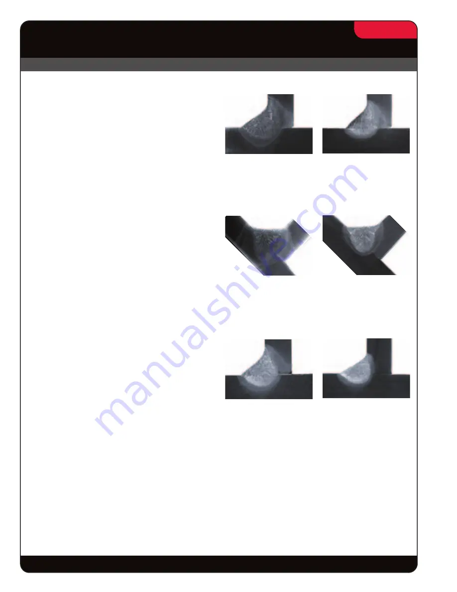
Figure 12
The weld on the left is DC+, 15 ipm travel.
The weld on the right is AC Balanced 25%, (-) 10% offset,
30 Hz., 21 ipm travel.
Figure 13
The weld on the left is with DC+, at 10.4 ipm travel.
The weld on the right is with AC 25% Balanced,
(-)20% Offset, 30Hz, at 15 ipm.
Figure 14
The weld on the left is with DC+.
The weld on the right is with AC 25% Balanced,
(-)10% Offset, 60Hz.
Some Fillet Weld Results`
A number of fillet welds made with the Power Wave
AC/DC 1000™ are shown as examples. All of these
welds comply with the AWS D1.1 Structural Steel
Code and the AWS D1.5 Bridge Code and those
codes that clone or refer to the AWS Codes.
All fillet welds conform to the acceptable size and
gauge size requirements of the code.There has been
no intent to match any specific mechanical properties,
however, the welding consumables used to produce
these welds are commonly used.
Figure 12: Horizontal, 5/16” (8mm) fillet welds, shows
an increase of 40% in travel speed over DC+. Both
welds made with 5/32” (4mm) diameter electrode at
527 amperes.
Figure 13: Flat positioned 1/2” (13mm) fillet welds
show an increase of 44% in travel speed over DC+.
Both welds made using 3/16” (4.8mm) diameter
electrode at 885 amperes.
Figure 14: Horizontal 1/4” (6mm) fillet welds, with an
increase of 32% in travel speed over DC+.