spool turns clockwise when the wire is fed into the wire
feeder.
Make sure that the spool locating pin goes into the
fitting hole on the spool.
Screw in the fastening cap of the sleeve.
Put on the wire roll using the correct groove
corresponding to the wire diameter.
Free the end of the wire and cut off the bent end
making sure it has no burr.
WARNING
Sharp end of the wire can hurt.
Rotate the wire spool clockwise and thread the end of
the wire into the wire feeder as far as the Euro socket.
Adjust force of pressure roll of the wire feeder properly.
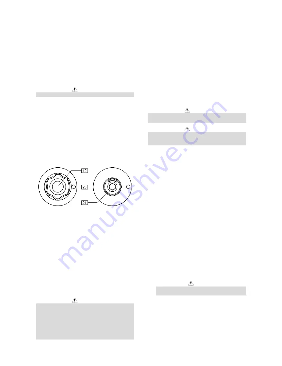
Adjustments of Brake Torque of
Sleeve
To avoid spontaneous unrolling of the welding wire the
sleeve is fitted with a brake.
Adjustment is carried by rotation of its screw M10,
which is placed inside of the sleeve frame after
unscrewing the fastening cap of the sleeve.
19. Fastening cap.
20. Adjusting screw M10.
21. Pressing spring.
Turning the screw M10 clockwise increases the spring
tension and you can increase the brake torque.
Turning the screw M10 counterclockwise decreases the
spring tension and you can decrease the brake torque.
After finishing of adjustment, you should screw in the
fastening cap again.
Adjusting of Force of Pressure Roll
Force
Pressure force is adjusted by turning the adjustment nut
clockwise to increase force, counterclockwise to
decrease force.
WARNING
If the roll pressure is too low the roll will slide on the
wire. If the roll pressure is set too high the wire may be
deformed, which will cause feeding problems in the
welding gun. The pressure force should be set
properly. Decrease the pressure force slowly until the
wire just begins to slide on the drive roll and then
increase the force slightly by turning of the adjustment
nut by one turn.
Inserting Electrode Wire into Welding
Torch
Connect the proper welding torch to the Euro socket,
the rated parameters of the torch and of the welding
source shall match.
Remove the gas diffuser and contact tip from the
welding torch.
Set the wire feeding speed in the position of about
10m/min by the WFS knob [2].
Switch the Cold Inch / Gas Purge switch [14] in the
position "Cold Inch" and keep in this position until the
electrode wire leaves the contact tip of the welding
torch.
WARNING
Take precaution to keep eyes and hands away from the
end of the torch while feeding wire.
WARNING
Once the wire has finished feeding through the welding
gun turn the wire supply off before replacing to contact
tip and gas diffuser.
Welding with MIG / MAG method
To begin welding process with MIG/MAG method in
manual mode you should:
•
Switch ON the machine which supplies the wire
feeder.
•
Insert the electrode wire into the torch using "Cold
Inch" switch [14].
•
Check gas flow with "Gas Purge" switch [14].
•
According to selected welding mode and material
thickness set the proper welding voltage with knob
[3] and the wire feeding speed with WFS knob [2].
•
Obeying the appropriate rules, you can begin to
weld.
Changing Driving Rolls
The wire feeder is equipped with drive rolls for the wire
of 1.0 and 1.2mm. For others wire sizes, is available
the proper drive rolls kit (see chapter Accessories for
ordering the desired kit). Below the drive rolls
replacement procedure:
•
Switch off the machine which supplies the wire
feeder.
•
Release the pressure roll lever [22].
•
Unscrew the fastening cap [23].
•
Open the protection cover [25].
•
Change the drive rolls [24] with the compatible
ones corresponding to the used wire.
WARNING
For wires with the diameter greater than 1.6mm,
the following parts are to be changed:
•
The guide tube of the feeding console [26] and
[27].
•
The guide tube of the Euro socket [28].
•
Replace and tighten the protection cover [25] to the
drive rolls.
•
Screw the protection cover by fastening screws
[23].
English
English
4


