Lincoln Electric K498 Manual Download Page 13

D-3

MAINTENANCE

D-3

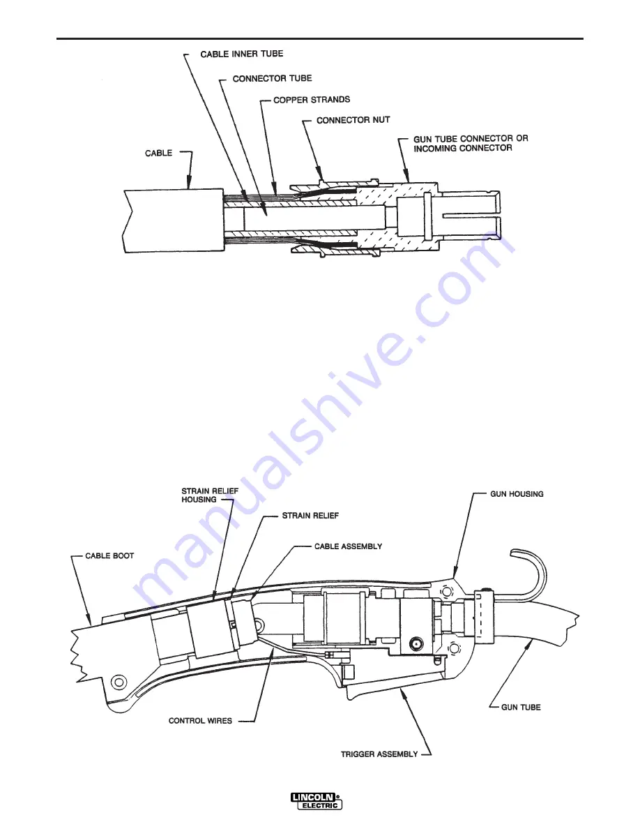
strain relief are on the cable. Slip the connector nut
over the copper strands with the thread end out.
Orient gun tube connector so machined flat is on
the same side of the cable as the red and white
control leads. Assemble gun tube connector to
cable by forcing the steel tube of the connector into
the inside diameter of the cable inner tube until the
copper strands are butted against the gun tube
connector shoulder. Keeping the copper strands
against the shoulder, pull the connector nut over
the copper strands, engage the gun tube connector
threads, and tighten in place. Refer to Figure 3.

NOTE:

For best results, insert a .175”/.197” (4.5-

5.0 mm) diameter rod through the connec-
tor and into core of cable approximately
5.00” (127 mm) when pushing the connec-
tor tube into the cable core tube. To tighten,
hold the connector in place while turning
the nut. Then remove the rod from the core.
This procedure ensures the inner core does
not kink while assembling or tightening.

h. Pull the cut-off lead terminals off the trigger assem-

bly and connect the replacement control lead termi-
nals.

i. Position the cable boot and strain relief on the

MAGNUM 200FM

FIGURE 3

FIGURE 4

Summary of Contents for K498

Page 1: ...n on your part DO NOT INSTALL OPERATE OR REPAIR THIS EQUIPMENT WITHOUT READ ING THIS MANUAL AND THE SAFETY PRECAUTIONS CON TAINED THROUGHOUT And most importantly think before you act and be careful Mo...

Page 2: ...WEARERS SHOULD CONSULT WITH THEIR DOCTOR BEFORE OPERATING Read and understand the following safety highlights For additional safety information it is strongly recommended that you purchase a copy of...

Page 3: ...cal earth ground 3 f Maintain the electrode holder work clamp welding cable and welding machine in good safe operating condition Replace damaged insulation 3 g Never dip the electrode in water for coo...

Page 4: ...vent the welding sparks from starting a fire Remember that welding sparks and hot materials from welding can easily go through small cracks and openings to adjacent areas Avoid welding near hydraulic...

Page 5: ...iv SAFETY iv Mar 93...

Page 6: ...ion below for future reference This information can be found on your machine nameplate Product _________________________________________________________________________________ Model Number __________...

Page 7: ...____________________________________________________________ Maintenance Section D Removal Installation and Trimming Instructions for Magnum Liners D 1 Gun Tubes and Nozzles D 1 Gun Cables D 2 Cable C...

Page 8: ...he procedure outlined in the Maintenance Section of this manual before working in that area of the equipment WARNING Choose the gas nozzle as appropriate for the GMAW process to be used Typically the...

Page 9: ...K498 1 15 ft 035 0 9 KP2020 1B1 KP2026 1 KP1935 2 KP2025 1 KP1934 1 KP2028 1 4 5 045 1 2 2B2 K498 2 10 ft 035 0 9 KP2020 1B1 KP2026 1 KP1935 2 KP2025 1 KP1934 1 KP2028 1 3 0 045 1 2 2B2 K498 3 15 ft...

Page 10: ...e gives the correct electrical stickout as required for the procedure being use d To stop welding release the gun trigger and then pull the gun away from the work after the arc goes out Follow wire fe...

Page 11: ...NSTALLATION AND TRIMMING INSTRUCTIONS FOR MAGNUM LINERS NOTICE The variation in cable lengths prevents the interchangeability of liners Once a liner has been cut for a particular gun it should not be...

Page 12: ...per Gun Tubes and Nozzles Section of pages D 1 and D2 c Remove three 6 screws from the gun handle sep arate the two halves and remove the cable from the handle along with the trigger assembly d Remove...

Page 13: ...ull the connector nut over the copper strands engage the gun tube connector threads and tighten in place Refer to Figure 3 NOTE For best results insert a 175 197 4 5 5 0 mm diameter rod through the co...

Page 14: ...past the damaged section Remove and save the cable clamp NOTE If sliding the cable handle becomes difficult try rotating it 180 e Remove incoming connector from cable by unscrewing connector nut from...

Page 15: ...g or tightening i Solder the terminal lead assemblies from step f to the control leads stripped in step g Insulate both soldered connections using either heat shrink tub ing or electrical tape j Fully...

Page 16: ...E CAUSE lists the obvious external possibilities that may contribute to the machine symptom Step 3 RECOMMENDED COURSE OF ACTION This column provides a course of action for the Possible Cause generally...

Page 17: ...ize cable liner h Partially flashed melted or improper size contact tip a Contact tip worn or incorrect size b Worn or undersize ground cables or poor ground connections c Loose electrode connections...

Page 18: ...seizes in diffuser a Improper procedures or tech niques b Improper gas shielding a Tip overheating due to prolonged or excessive high current and or duty cycle welding a See Gas Metal Arc Welding Guid...

Page 19: ...NOTES MAGNUM 200FM...

Page 20: ...electrically live parts or electrode with skin or wet clothing Insulate yourself from work and ground No toque las partes o los electrodos bajo carga con la piel o ropa moja da Aislese del trabajo y...

Page 21: ...e Be und Entl ftung des Arbeitsplatzes Mantenha seu rosto da fuma a Use ventila o e exhaust o para remover fumo da zona respirat ria Turn power off before servicing Desconectar el cable de ali mentaci...

Page 22: ...and Service through Subsidiaries and Distributors Worldwide Cleveland Ohio 44117 1199 U S A TEL 216 481 8100 FAX 216 486 1751 WEB SITE www lincolnelectric com World s Leader in Welding and Cutting Pr...

Reviews: