background image

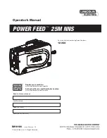
Operator’s Manual

POWER FEED 

25M NNS

Register your machine:  

www.lincolnelectric.com/register

Authorized Service and Distributor Locator:  

www.lincolnelectric.com/locator

IM10180

|   Issue D ate Jan- 14

© Lincoln Global, Inc.  All Rights Reserved.

For use with machines having Code Numbers:

12244

Save for future reference  

Date Purchased

Code: (ex: 10859)

Serial: (ex: U1060512345)

Summary of Contents for K2536-6

Page 1: ...c com register Authorized Service and Distributor Locator www lincolnelectric com locator IM10180 Issue Date Jan 14 Lincoln Global Inc All Rights Reserved For use with machines having Code Numbers 12244 Save for future reference Date Purchased Code ex 10859 Serial ex U1060512345 ...

Page 2: ...N A LARGE ROOM OR OUTDOORS natural ventilation may be adequate if you keep your head out of the fumes See below USE NATURAL DRAFTS or fans to keep the fumes away from your face If you develop unusual symptoms see your supervisor Perhaps the welding atmosphere and ventilation system should be checked WEAR CORRECT EYE EAR BODY PROTECTION PROTECT your eyes and face with welding helmet properly fitted...

Page 3: ... hot engine parts and igniting Do not spill fuel when filling tank If fuel is spilled wipe it up and do not start engine until fumes have been eliminated 1 d Keep all equipment safety guards covers and devices in position and in good repair Keep hands hair clothing and tools away from V belts gears fans and all other moving parts when starting operating or repairing equipment 1 e In some cases it ...

Page 4: ...rm to ANSI Z87 I standards 4 b Use suitable clothing made from durable flame resistant material to protect your skin and that of your helpers from the arc rays 4 c Protect other nearby personnel with suitable non flammable screening and or warn them not to watch the arc nor expose themselves to the arc rays or to hot spatter or metal FUMES AND GASES CAN BE DANGEROUS 5 a Welding may produce fumes a...

Page 5: ...ent passing through lifting chains crane cables or other alternate circuits This can create fire hazards or overheat lifting chains or cables until they fail 6 h Also see item 1 c 6 I Read and follow NFPA 51B Standard for Fire Prevention During Welding Cutting and Other Hot Work available from NFPA 1 Batterymarch Park PO box 9101 Quincy MA 022690 9101 6 j Do not use a welding power source for pipe...

Page 6: ... is compatible This may require additional protection measures h the time of day that welding or other activities are to be carried out The size of the surrounding area to be considered will depend on the structure of the building and other activities that are taking place The surrounding area may extend beyond the boundaries of the premises methods oF reduCing emissions Mains Supply Welding equip...

Page 7: ...ru B 20 Set Up Feature Menu for Parameters and Definition B 21 thru B 27 Dual Procedure Memory Buttons B 28 thru B 30 Internal Controls B 31 Cold Feed Gas Purge Switch Light Switch Heater Switch Pressure Arm Adjustment B 32 Rear Controls B 33 ________________________________________________________________________________ Accessories Section C Factory Installed Equipment C 1 Drive Roll Kits C 1 __...

Page 8: ...R FEED 25M NNS is the MAXtrac drive The patented features on the wire drive offer tool less changing of the drive rolls and the wire guides for quick spool changes The POWER FEED 25M NNS continues Lincoln s lead role of environmental protection for electronics P C boards are potted in epoxy and electrical connections are protected with dielectric grease Noise suppression components protect the POW...

Page 9: ...hes 8 5 Inches 23 5 Inches 35 lbs 368 mm 216 mm 597 mm 15 9 kg Handle folded down GEARING WIRE FEED SPEED RANGE WIRE SIzE PHySICAL DIMENSIONS WFS RANGE 50 800 ipm 2 5 20 3m min WFS RANGE 50 800 ipm 2 5 20 3m min WIRE SIzES 023 1 16 0 6 1 6mm WIRE SIzES 030 5 64 0 8 2 0mm INPUT VOLTAGE 10 40 VDC INPUT AMPERES 4A RATED OUTPUT 104 F 40 C DUTy CyCLE 60 rating GEARING Normal Speed factory setting INPUT...

Page 10: ...ely controlled Do not operate with covers panels or guards removed Do not let the electrode or wire spool touch the wire feeder housing Insulate yourself from the work and ground Always wear dry insulating gloves WARNING METAL TAB OF THE WELDING GUN THUMB SCREW The metal tab of the welding gun and thumb screw securing the gun are at electrode potential when the welding output is on Do not touch th...

Page 11: ...ich may result in bodily injury or damage to the equip ment CABLE CONNECTION There is one connector on the front of the POWER FEED 25M NNS for the gun trigger See 2 prong Figure A 2 ARCLINK CONTROL CABLES There is one circular connector on the rear of the POWER FEED 25M NNS Maximum control cable length is 200 ft 61 m See Figure A 3 See Figure A 4 ArcLink LincNet control cables are special high qua...

Page 12: ...nnection and the other end to the wire feeder electrode connec tion 3 Connect the outer lead bundle to the power source work connection and the other end to the work piece Minimize the length of any work lead extension for best results 4 Insulate all connections E El le ec ctr tro od de e W Wo or rk k W Wo or rk k Electrode Electrode W Work ork Electrode Electrode W Work ork Power Source Power Sou...

Page 13: ...fitting of the flow reg ulator Attach the other end to the welding system shielding gas inlet Tighten the union nuts with a wrench 6 Before opening the cylinder valve turn the regulator adjusting knob counterclockwise until the adjusting spring pressure is released 7 Standing to one side open the cylinder valve slowly a fraction of a turn When the cylinder pressure gage stops moving open the valve...

Page 14: ...et the wire size and wire feed speed the same for all the arcs When these parameters are identical the pulsing frequency will be the same helping to stabilize the arcs LOADING SPOOLS OF WIRE Keep hands hair clothing and tools away from rotating equipment Do not wear gloves when threading wire or changing wire spool Only qualified personnel should install use or service this equipment Loading 10 to...

Page 15: ...sure Patented split wire guides fully support the wire and virtually eliminate birdnesting No tools required to change the drive rolls and wire guides Patented dual spring pressure arms have sensitivity for feed ing soft wires without crushing them and have plenty of com pression force for feeding solid or stiff wires All gear driven rolls for more feeding force Powerful quiet motor with integrate...

Page 16: ...uards removed or open Only qualified personnel should perform main tenance work FUMES AND GASSES can be dangerous Keep your head out of fumes Use ventilation or exhaust to remove fumes from breathing zone WELDING SPARKS can cause fire or explosion Keep flammable material away ARC RAyS can burn Wear eye ear and body protec tion SEE ADDITIONAL WARNING INFORMATION UNDER ARC WELDING SAFETy PRECAUTIONS...

Page 17: ...et by the operator WFS Wire Feed Speed CC Constant Current CV Constant Voltage GMAW Gas Metal Arc Welding GMAW P Gas Metal Arc Welding Pulse Arc GMAW STT Gas Metal Arc Welding Surface Tension Transfer SMAW Shielded Metal Arc Welding FCAW Flux Core Arc Welding CAG Carbon Arc Gouging DUTY CYCLE The POWER FEED 25M NNS is rated for 500 amps 60 duty cycle The duty cycle is based on a 10 minute cycle Fo...

Page 18: ...e power sources Maximum gun length is 25ft 7 6m for push only systems Maximum spool size is 12 in 305 mm diameter Maximum spool weight is 44 lb 20 kg Maximum control cable length is 200 ft 61 m No more than 2 wire feeders may be connected to one ArcLink power source at a time RECOMMENDED POWER SOURCES Power Wave 355M Power Wave 455M Power Wave 455M STT Power Wave S350 Power Wave R350 Power Wave i4...

Page 19: ...peration 7 Gun Shielding Gas Connections 8 ON OFF switch Controls power to the POWER FEED 25M NNS 9 Gun Electrode Connection 10 Gun Trigger Connection 11 Right Display window Shows VOLTAGE or TRIM 12 Right Knob Adjusts values in the right display 13 Thermal Lights when the drive overheats 14 Set Up Lights when feeder is set up 15 Right Button Changes the Main display to show Start Options or End O...

Page 20: ...weld ing procedure plate chemistry and temperature weldment design fabrication methods and service requirements The avail able range of a welding program may not be suitable for all applications and the build user is and must be solely responsi ble for welding program selection The steps for operating the Power Wave will vary depending upon the user interface of the welding system The flexibility ...

Page 21: ...PLAY AND KNOB The left display and knob are used to adjust either wire feed speed or amperage depending upon the process selected While welding the amps LED lights when amperage is displayed and the wire feed speed LED lights when WFS is displayed FIGURE B 2 ...

Page 22: ...en the voltage knob is rotated the display will show an upper or lower bar indicat ing if the voltage is above or below the ideal voltage The display is blank for synergic STT modes Preset voltage above ideal voltage upper bar displayed Preset voltage at idealvoltage no bar displayed Preset voltage below idealvolt age lower bar displayed VOLTAGE TRIM DISPLAY AND KNOB The right display and knob con...

Page 23: ...usted the Power Wave auto matically recalculates the voltage current and time of each part of the pulse waveform for the best result Trim adjusts the arc length and ranges from 0 50 to 1 50 Increasing the trim value increases the arc length while decreasing the trim value decreases the arc length VOLTAGE TRIM DISPLAY AND KNOB Trim 50 Arc Length Short Trim 1 00 Arc Length Medium Trim 1 50 Arc Lengt...

Page 24: ...unction 1 Rotate the center knob until Weld Mode Search is displayed and then press the right button 2 Rotate the center knob to select the wire material Press the right button to accept and the left button to cancel 3 Rotate the center knob to select the wire size Press the right button to accept and the left button to cancel 4 Rotate the center knob to make the final selection about the process ...

Page 25: ...ing Ultimarc regulates the focus or shape of the arc Ultimarc values greater than 0 0 increase the pulse frequency while decreasing the background current resulting in a tight stiff arc best for high speed sheet metal welding Ultimarc values less than 0 0 decrease the pulse frequency while increasing the back ground current for a soft arc good for out of position welding For Pulse modes Arc Contro...

Page 26: ...est practice is to adjust for minimum spatter and puddle agitation Peak also affects the shape of the root When using 100 CO2 the peak cur rent will be higher than when welding with blended shielded gases A longer arc length is required with CO2 to reduce spatter Background current adjusts the overall heat input into the weld Changing the background current changes the shape of the back bead 100 C...

Page 27: ...trigger has no effect when welding with SMAW or CAG procedures 2 Step Trigger 2 Step trigger operation is the most common When the gun trigger is pulled the welding system power source and wire feeder cycles through the arc starting sequence and into the main welding parameters The welding system will continue to weld as long as the gun trigger is activated Once the trigger is released the welding...

Page 28: ...h a 2 Step trigger and Start and Crater set to OFF For this sequence PREFLOW Shielding gas begins to flow immediately when the gun trigger is pulled RUN IN After preflow time expires the power source regulates to the welding output and wire is advanced towards the work piece at the Run In WFS If an arc is not established within 2 0 seconds the wire feed speed will jump to the welding wire feed spe...

Page 29: ... If an arc is not established within 2 0 seconds the power source output and wire feed speed skips to the weld settings START Once the wire touches the work and an arc is established both the machine output and the wire feed speed ramp to the weld settings throughout the start time The time period of ramping from the start settings to the weld settings is called UPSLOPE WELD After upslope the powe...

Page 30: ...ngs is called UPSLOPE WELD After upslope the power source output and the wire feed speed continue at the weld settings BURNBACK After the crater time expires the wire feed speed is turned OFF and the machine output continues for the burn back time POSTFLOW Next the machine output is turned OFF and shielding gas continues until the post flow timer expires 2 Step trigger Special considerations The w...

Page 31: ... long welds by allowing the trigger to be released after an initial trigger pull Welding stops when the trigger is pulled a second time and then released or if the arc is interrupted For this sequence PREFLOW Shielding gas begins to flow immediately when the gun trigger is pulled RUN IN After preflow time expires the power source regulates to the welding output and wire is advanced towards the wor...

Page 32: ...peed skips to the weld settings START The power source welds at the start WFS and voltage until the trigger is released UPSLOPE During upslope the power source output and the wire feed speed ramp to the weld settings throughout the start time The time period of ramping from the start settings to the weld settings is called UPSLOPE If the trigger is pulled before upslope is complete WELD is skipped...

Page 33: ...splay will be blank and the right display will show OFF The Spot Time LED from the timer menu will blink twice After 2 0 seconds the trigger menu cycles back to the Cold Feed Trigger option If Start is not set to OFF the left display will be blank and the right display will show On The Start LED from the sequence menu will blink twice After 2 0 seconds the trigger menu cycles back to the Cold Feed...

Page 34: ...elease occurs during UPSLOPE the sequencer will jump to the BURNBACK to end the weld Example 2 Pull the trigger to start feed of wire When arc is established the sequencer will remain in START until the trigger is released When the trigger is released UPSLOPE begins and continues into WELD when the START timer is complete When the trigger is pulled again step 3 and CRATER DOWNSLOPE is active DOWNS...

Page 35: ...lux cored GTAW TIG Start Options Spot Timer Crater Time WFS and Volts Burnback Time Postflow Time Postflow Time Effect Range 0 10 0 seconds Auto 0 0 25 seconds 0 25 0 seconds 0 25 0 seconds Description Sets the length of time for welding when the trigger is pulled If the trigger is released before the Spot Timer is complete welding stops This option has no effect in 4 Step Trigger Mode Crater Proc...

Page 36: ...e Diagnostic Parameters always read only Secured Parameters only accessible through a p c or palm application GTAW TIG WELDING The POWER FEED Power Wave system is excel lent for Touch Start TIG welding The system supports TIG torches with or without gas control valves TIG torches with gas control valves connect directly to the gas flow regulator For TIG torches without gas control valves connect t...

Page 37: ... P 3 selections will be available on all machines In order for each selection to be included in the list the power source must support that feature A software update of the power source may be needed to include the features Standard Display The lower displays will continue to show preset information during and after a weld default Show Energy Energy is displayed along with time in HH MM SS format ...

Page 38: ...ff and the Postflow time expires P 9 Crater Delay This option is used to skip the Crater sequence when making short tack welds If the trigger is released before the timer expires Crater will be bypassed and the weld will end If the trigger is released after the timer expires the Crater sequence will function normally if enabled P 14 Reset Consumable Weight Use this option to reset the initial weig...

Page 39: ...liano Deutsch Francais Polski Espanol P 28 Display Workpoint as Amps Option This option determines how workpoint is displayed False The workpoint is displayed in the format defined in the weld set default True All workpoint values are displayed as an amperage Note This option may not be available on all machines The power source must support this functionality or this option will not appear in the...

Page 40: ...umber event code and some other data Press the Left Button to back out to select another log Press the Left Button again to exit this option P 102 View Fatal Logs Used for viewing all the system fatal logs Press the Right Button to enter the option Rotate Control Knob to select the desired fatal log to read Press the Right Button again to enter that log Rotating the Control Knob will scroll throug...

Page 41: ...Lockout Locks one or both of the upper knobs encoders preventing the operator from changing wire feed speed amps volts or trim The function of each upper knob depends on the selected weld mode When a constant current weld mode is selected e g Stick TIG Gouge the upper right knob will always function as an on off switch This parameter can only be accessed using Power Wave Manager software P 502 Mem...

Page 42: ...ked Start End Mode Options Locked The Start End and Weld Mode Select parameters on the Mode Select Panel are locked all others are unlocked This parameter can only be accessed using Power Wave Manager software P 505 Setup Menu Lock Determines if the setup parameters can be modified by the operator without entering a pass code No The operator can change any set menu parameter without first entering...

Page 43: ...y DUAL PROCEDURE MEMORy PANEL OPERATION The Dual Procedure Memory Panel performs three functions Weld procedure selection Memory save and recall Limits setting There are two procedure memories A and B and eight user memories 1 8 Procedure Memory vs User Memory Procedure memory is used while welding Changes to the weld procedure WFS voltage UltimArc Controll etc immediately change the contents insi...

Page 44: ...ts or by setting memory limits When memory limits are enabled the parameter will flash whenever an attempt is made to exceed the memory limit value The para meter will not flash if an attempt is made to exceed the machine limit The system machine limits are Parameter Wire Feed Speed Voltage Trim UltimArc Preflow Start Time Run In WFS Crater Time Burnback Time Postflow Time Range Weld mode and wire...

Page 45: ...S SET SETUP WELD MODE ARC CONTROL Memory Value Parameter Name Low Limit High Limit The memory value must always be less than or equal to the high limit and greater than or equal to the low limit After setting limits press the memory button with the flashing LED The display will ask to save or discard the limit changes just made Press the left user inter face for button YES to save and enable the l...

Page 46: ...TERNAL CONTROLS 1 Cold Feed Gas Purge Switch 2 Wire Drive Pressure Arm 3 Internal Light Switch 4 Internal Heater Switch 5 Spindle Brake 6 Gun Adapter ITEM DESCRIPTION 1 1 7 7 6 6 3 3 2 2 7 Thumb Screw for securing the Gun Adapter 4 4 5 5 ...

Page 47: ... OFF COLD FEED GAS PURGE ROCKER SWITCH LIGHT ROCKER SWITCH HEATER ROCKER SWITCH G7937 2 VM COLD FEED GAS PURGE LIGHTS HEATER ON OFF ON OFF COLD FEED GAS PURGE ROCKER SWITCH LIGHT ROCKER SWITCH HEATER ROCKER SWITCH G7937 2 VM COLD FEED GAS PURGE LIGHTS HEATER ON OFF ON OFF COLD FEED GAS PURGE ROCKER SWITCH LIGHT ROCKER SWITCH HEATER ROCKER SWITCH PRESSURE ARM ADJUSTMENT ELECTRIC SHOCK can kill Turn...

Page 48: ...B 33 OPERATION POWER FEED 25M NNS REAR CONTROLS 1 Shielding Gas Inlet 2 ArcLink Cable Connector 3 Electrode Cable ITEM DESCRIPTION 1 2 3 ...

Page 49: ...4 Smooth V groove drive rolls and inner wire guide drive roll Kits Cored wires KP1505 035C 030 035 0 8 0 9mm KP1505 045C 040 045 1 0 1 2mm KP1505 052C 052 1 4mm KP1505 1 16C 1 16 1 6mm Includes 4 Knurled drive rolls and inner wire guide drive roll Kits steel or Cored wires KP1505 068 068 072 1 8mm KP1505 5 64 5 64 2 0mm KP1505 3 32 3 32 2 4mm KP1505 7 64 7 64 2 8mm KP1505 120 120 3 2mm Includes 4 ...

Page 50: ... are less than 0 5 12 7 mm long CALIBRATION SPECIFICATION All calibrations are factory set on the POWER FEED 25M NNS To verify the wire feed speed Assemble a 045 1 2mm drive roll kit into the POWER FEED 25M NNS Load a spool of 045 1 2mm electrode and thread the electrode through the wire drive Adjust the wire feed speed to 300 in min 7 62m min Press the COLD FEED switch and measure the actual wire...

Page 51: ...SE lists the obvious external possibilities that may contribute to the machine symptom Step 3 RECOMMENDED COURSE OF ACTION This column provides a course of action for the Possible Cause generally it states to contact your local Lincoln Authorized Field Service Facility If you do not understand or are unable to perform the Recommended Course of Action safely contact your local Lincoln Authorized Fi...

Page 52: ...usually because the motor is in a locked rotor state 1 The power source does not have any welding programs loaded Possible Adjustments 1 Verify the power source is operat ing properly Status light steady green 2 Check control cable for loose or broken leads 3 See power source Instruction Manual 1 Verify the power source is operat ing properly Status light steady green 2 Check control cable for loo...

Page 53: ... dirty 5 The contact tip is partially melted or has spatter 6 Improper gun liner tip drive rolls and or inner wire guide 7 Incorrect tension arm pressure on the drive rolls 8 Worn drive roll 1 Turn the POWER FEED 25M NNS power switch ON 2 Turn ON the Power Wave power source 3 Reset the circuit breakers 4 Tighten repair or replace the con trol cable 5 Replace the power switch 1 Verify the gas suppl...

Page 54: ...nothing during welding 1 Wrong size worn and or melted contact tip 2 Worn work cable or poor work connection 3 Wrong polarity 4 The gas nozzle is extended beyond the contact tip or the wire stickout is too long 5 Poor gas shielding on processes requiring gas 1 Improper procedures or tech niques 1 The software in the POWER FEED 25M NNS must be upgraded 1 Replace the contact tip 2 Verify all work an...

Page 55: ...It may not be accurate for all machines covered by this manual The specific diagram for a particular code is pasted inside the machine on one of the enclosure panels If the diagram is illegible write to the Service Department for a replacement Give the equipment code number ...

Page 56: ...F 2 DIAGRAMS POWER FEED 25M NNS 12 X 18 In Ellipse 16 In Circle 23 1 17 2 14 8 8 7 5 7 17 2 14 8 ...

Page 57: ...parts or electrode with skin or wet clothing l Insulate yourself from work and ground l No toque las partes o los electrodos bajo carga con la piel o ropa moja da l Aislese del trabajo y de la tierra l Ne laissez ni la peau ni des vête ments mouillés entrer en contact avec des pièces sous tension l Isolez vous du travail et de la terre l Berühren Sie keine stromführenden Teile oder Elektroden mit ...

Page 58: ... und Entlüftung des Arbeitsplatzes l Mantenha seu rosto da fumaça l Use ventilação e exhaustão para remover fumo da zona respiratória l Turn power off before servicing l Desconectar el cable de ali mentación de poder de la máquina antes de iniciar cualquier servicio l Débranchez le courant avant l entre tien l Strom vor Wartungsarbeiten abschalten Netzstrom völlig öff nen Maschine anhalten l Não o...

Page 59: ...stomer s particular purpose with respect to such information or advice As a matter of practical consideration we also cannot assume any responsibility for updating or correcting any such information or advice once it has been given nor does the provision of information or advice create expand or alter any warranty with respect to the sale of our products Lincoln Electric is a responsive manufactur...

Reviews:

Related manuals for K2536-6