


English 8 English
Changing Driving Rolls
The wire feeder is equipped with drive rolls for the wire of
1.0 and 1.2mm. For others wire sizes, is available the
proper drive rolls kit (see chapter Accessories for ordering
the desired kit). Below the drive rolls replacement
procedure:
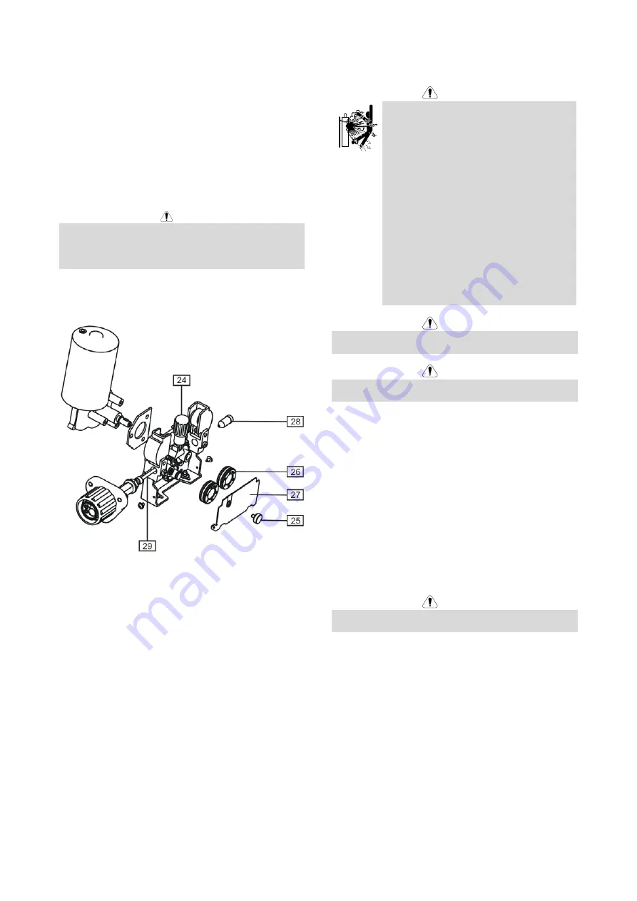
Switch off the machine which supplies the wire feeder.
Release the pressure roll lever [24].
Unscrew the fastening cap [25].
Open the protection cover [27].
Change the drive rolls [26] with the compatible ones
corresponding to the used wire.
WARNING
For wires with the diameter greater than 1.6mm, the
following parts are to be changed:
The guide tube of the feeding console [28].
The guide tube of the Euro socket [29].
Replace and tighten the protection cover [27] to the
drive rolls.
Screw the protection cover by fastening screws [25].
Gas Connection
WARNING
CYLINDER may explode if damaged.
Always fix the gas cylinder securely in an
upright position, against a cylinder wall
rack or purpose-made cylinder cart.
Keep cylinder away from areas where it
may be damaged, heated or electrical
circuits to prevent possible explosion or
fire.
Keep cylinder away from welding or other
live electrical circuits.
Never lift welder with cylinder attached.
Never allow welding electrode to touch
cylinder.
Build up of shielding gas may harm health
or kill. Use in a well-ventilated area to
avoid gas accumulation.
Close the gas cylinder valves thoroughly
when not in use to avoid leaks.
WARNING
Welding machine supports all suitable shielding gases at
a maximum pressure of 5,0 bar.
WARNING
Before use, make sure that the gas cylinder contains gas
suitable for the intended purpose.
Turn off input power at the welding power source.
Install a proper gas flow regulator to the gas cylinder.
Connect the gas hose to the regulator using the hose
clamp.
The other end of the gas hose connect to the gas
connector on the power source rear panel or directly
to the quick connector located on the rear panel of the
wire feeder [12]. More details you will find in power
source instruction manual.
Connect by dedicated interconnection cable (see
„Accessories
ʺ
chapter) wire feeder and power source.
Turn on input power at the welding power source.
Open the gas cylinder valve.
Adjust the shielding gas flow of the gas regulator.
Check gas flow with Gas Purge Switch [15].
WARNING
To weld GMAW process with CO
2
shielding gas, CO
2
gas
heater should be used.


