


A-4
INSTALLATION
IDEALARC SP-255 OCT94
However, the thumbswitch functions available on
the Magnum 250SP gun will only be operable from
the front panel keypad. The gun trigger switch must
be capable of switching 5 milliamps at 15 volts
DC– resistive.
The gun trigger switch connected to the gun trig-
ger control cable must be a normally open,
momentary switch. The terminals of the switch
must be insulated from the welding circuit.
Improper operation of or damage to the SP-255
might result if this switch is common to an electri-
cal circuit other than the SP-255 trigger circuit.
SHIELDING GAS
(For Gas Metal Arc Welding Processes)
Customer must provide cylinder of appropriate type
shielding gas for the process being used.
1. Set gas cylinder in rear platform of SP-255. Hook
chain in place to secure cylinder to rear of welder.
2. Remove the cylinder cap. Inspect the cylinder
valves for damaged threads, dirt, dust, oil or
grease. Remove dust and dirt with a clean cloth.
DO NOT ATTACH THE REGULATOR IF OIL,
GREASE OR DAMAGE IS PRESENT! Inform your
gas supplier of this condition. Oil or grease in the
presence of high pressure oxygen is explosive.
3. Stand to one side away from the outlet and open
the cylinder valve for an instant. This blows away
any dust or dirt which may have accumulated in the
valve outlet.
Be sure to keep your face away from the valve
outlet when “cracking” the valve.
4. Inspect the regulator for damaged threads, dirt,
dust, oil or grease. Remove dust and dirt with a
clean cloth.
DO NOT USE THE REGULATOR IF OIL,
GREASE OR DAMAGE IS PRESENT! Have an
authorized repair station clean the regulator or
repair any damage.
5. Attach the flow regulator to the cylinder valve and
tighten the union nut(s) securely with a wrench.
NOTE:
If connecting to 100% CO
2
cylinder, insert
regulator adapter provided between regulator and
cylinder valve. If adapter is equipped with a plastic
washer, be sure it is seated for connection to the
CO
2
cylinder.
6. Attach one end of the inlet gas hose to the outlet
fitting of the flow regulator, the other end to the SP-
255 rear fitting, and tighten the union nuts securely
with a wrench.
7. Before opening the cylinder valve, turn the regula-
tor adjusting knob counter-clockwise until the
adjusting spring pressure is released.
8. Open the cylinder valve slowly a fraction of a turn.
When the cylinder pressure gauge pointer stops
moving, open the valve fully.
Never stand directly in front of or behind the flow
regulator when opening the cylinder valve. Always
stand to one side.
9. The flow regulator is adjustable. Set it for the flow
rate recommended for the procedure and process
being used before making the weld.
CAUTION
CYLINDER may explode if
damaged.
Gas under pressure is explosive.
Always keep gas cylinders in an
upright position and always keep
chained to undercarriage or stationary support.
See American national Standard Z49.1, “Safety in
Welding and Cutting” published by the American
Welding Society.
WARNING
WARNING
WARNING
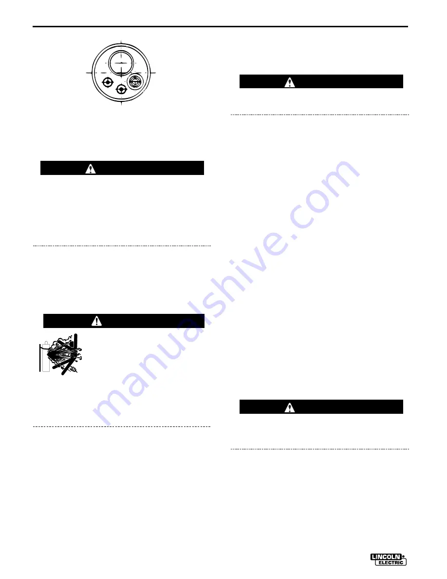
Gun - END VIEW
Summary of Contents for IDEALARC SP-255
Page 32: ...C 4 NOTES IDEALARC SP 255...
Page 36: ...D 4 NOTES IDEALARC SP 255...
Page 45: ...F 3 DIMENSION PRINT IDEALARC SP 255 SP 255 DIMENSION PRINT M16352 1 31 92B Inches Millimeters...
Page 46: ...NOTES...
Page 47: ...NOTES...
Page 48: ...NOTES...
Page 49: ...NOTES...


