F-3
WIRING DIAGRAMS
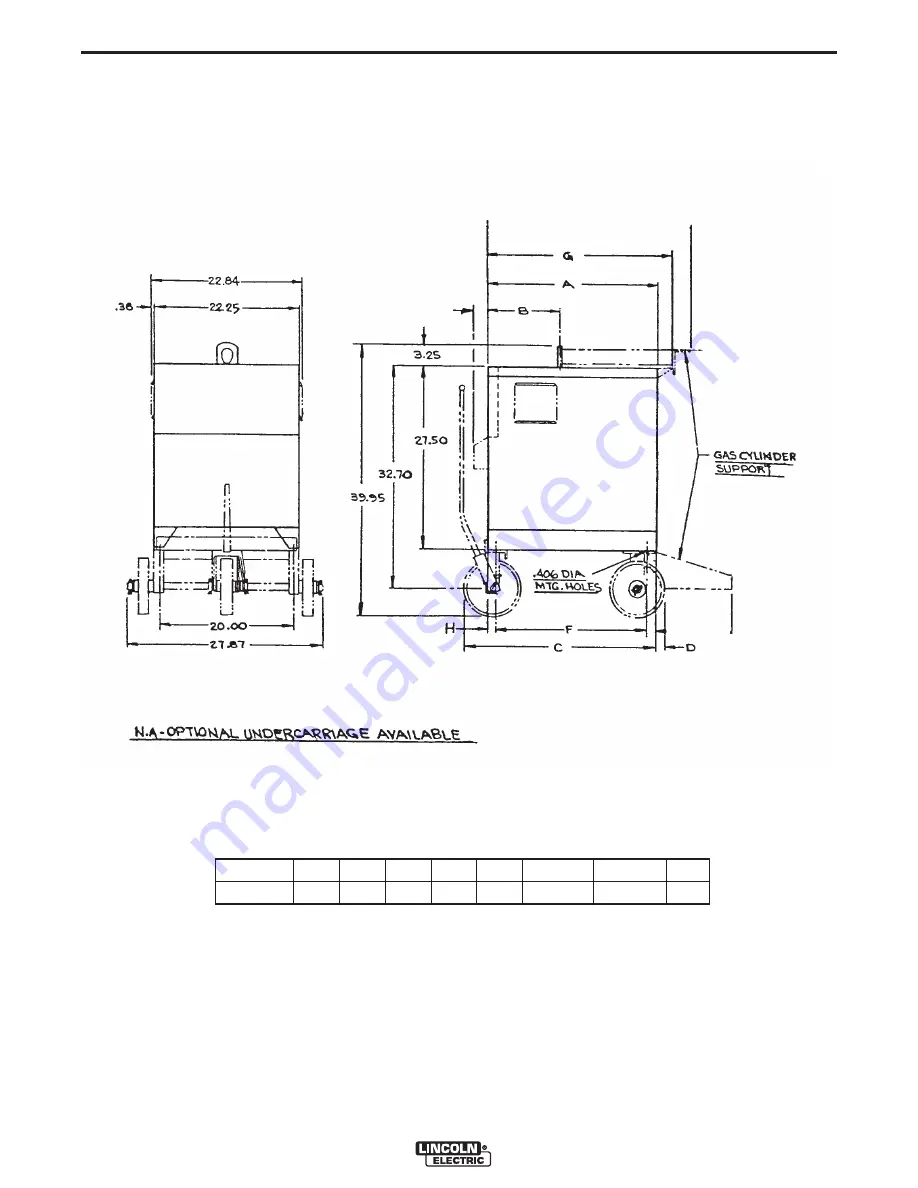
IDEALARC® R3R 375-I, 500-I AND 600-I
R3R 375-I, 500-I and 600-I
K817 or K817R
(K841 not shown)
Part No.
Type
A
B
C
D
F
G
H
M12244-7
R3R
32.00 15.39
3092
1.44
30.02±.11
33.07±.06
.94
M12244-77-7-78
Page 1: ...r part DO NOT INSTALL OPERATE OR REPAIR THIS EQUIPMENT WITHOUT READ ING THIS MANUAL AND THE SAFETY PRECAUTIONS CON TAINED THROUGHOUT And most importantly think before you act and be careful For use wi...
Page 2: ...R WEARERS SHOULD CONSULT WITH THEIR DOCTOR BEFORE OPERATING Read and understand the following safety highlights For additional safety information it is strongly recommended that you purchase a copy of...
Page 3: ...oling 3 h Never simultaneously touch electrically hot parts of electrode holders connected to two welders because voltage between the two can be the total of the open circuit voltage of both welders 3...
Page 4: ...ks and openings to adjacent areas Avoid welding near hydraulic lines Have a fire extinguisher readily available 6 b Where compressed gases are to be used at the job site special precautions should be...
Page 5: ...appropri s et non inflammables 4 Des gouttes de laitier en fusion sont mises de l arc de soudage Se prot ger avec des v tements de protection libres de l huile tels que les gants en cuir chemise pais...
Page 6: ...important when identifying the correct replacement parts On Line Product Registration Register your machine with Lincoln Electric either via fax or over the Internet For faxing Complete the form on th...
Page 7: ...lation Section A Input Power Connection A 1 Duty Cycle A 1 Output Connections A 1 Operating Instructions Section B Accessories Section C Maintenance Section D Troubleshooting Section E Troubleshooting...
Page 8: ...nd lead to the ground stud marked with the symbol Install the reconnect panel for the proper input voltage per the diagram pasted inside the access panel cover DUTY CYCLE The maximum output rating of...
Page 9: ...ol dial labeled I on the front of the machine indicates the output current On the R3R 375 I there is only one dial On the R3R 500 I and 600 I there are two dials The A range controls the current over...
Page 10: ...WITCH Remote Output Current Control F POLARITY SWITCH Factory installed option on domestic models only Electrode Polarity Positive Electrode Polarity Negative Do Not Switch While Welding G RATING PLAT...
Page 11: ...ROL AND K870 FOOT AMPTROL Connect directly to the 6 pin Amphenol on the front of the power source POCKET AMPTROL factory installed only The Pocket Amptrol option provides a remote current control for...
Page 12: ...required The probe tip should be kept in condition to provide sharp edges at the ends to assure penetration of heavy oxide coatings on the work piece A blunted tip could result in giving different wel...
Page 13: ...i ties that may contribute to the machine symptom Step 3 RECOMMENDED COURSE OF ACTION This column provides a course of action for the Possible Cause If you do not understand or are unable to perform t...
Page 14: ...ed 6 Input contactor coil open 7 Open winding on 115V pilot transformer 8 Power ON OFF switch not closing 9 Lead broken or loose connec tion in 115V starter circuit 10 Thermostats defective High Tempe...
Page 15: ...Electrode or work lead loose or broken 2 Open transformer primary or secondary circuit 3 Supply line fuse blown 4 Input line grounded causing single phase input 5 Input leads not connected to contact...
Page 16: ...Troubleshooting Section E 1 Input fuse blown Machine is single phased 2 One phase of main transformer windings open 3 Defective power bridge 1 Improper ventilation 2 Loaded beyond rating 3 Fan inoper...
Page 17: ...baffle 1 Poor work or electrode cable connection 2 Current too low 3 Welding leads too small 4 Open SCR or diode in power rectifier bridge 5 Control circuit problems 1 Input contactor contacts frozen...
Page 18: ...COURSE OF ACTION L Optional remote current control not functioning See Troubleshooting Section C before connecting 1 Current control switch in the wrong position 2 Leads 75 76 and 77 not con nected t...
Page 19: ...ng and replacing check repair are OK one at a time changes OCV each gate lead one at a time does NOT change OCV Codes below 9500 with power off remove leads from Identify gate lead that when Codes abo...
Page 20: ...rent control rheostat or the control circuit Only the green lead can and should be grounded to the machine case When extending the standard remote control make sure the leads are the same and the spli...
Page 21: ...crew Reading should be infinite 5 If either step 3 or step 4 fails replace the switch I REMOTE CONTROL CHECK For codes above 9500 the remote control Amphenol pin assignments are pin C 75 pin B 76 and...
Page 22: ...d a much higher resistance in Step c K POWER SILICON CONTROLLED REC TIFIER TEST The SCR must be mounted in the heat sink when making this test a Connect the ohmmeter set to the X10 scale leads to the...
Page 23: ...4 5 6 66V BOTTOM PRIMARY TOP PRIMARY T1 X1 X2 X3 SEC SEC SEC 16 17 18 ARE PRESENT ON 380 500 OR 460 575 MACHINES ONLY THERE IS NO 10 11 12 CONNECTION ON 380 A CHOKE THERMOSTAT SECONDARY THERMOSTAT 23...
Page 24: ...375 I 500 I AND 600 I F 2 NOTE This diagram is for reference only It may not be accurate for all machines covered by this manual The specific diagram for a particular code is pasted inside the machin...
Page 25: ...RING DIAGRAMS IDEALARC R3R 375 I 500 I AND 600 I F 3 R3R 375 I 500 I and 600 I K817 or K817R K841 not shown Part No Type A B C D F G H M12244 7 R3R 32 00 15 39 3092 1 44 30 02 11 33 07 06 94 M12244 7...
Page 26: ...CHTEN Do not touch electrically live parts or electrode with skin or wet clothing Insulate yourself from work and ground No toque las partes o los electrodos bajo carga con la piel o ropa moja da Aisl...
Page 27: ...Sorgen Sie f r gute Be und Entl ftung des Arbeitsplatzes Mantenha seu rosto da fuma a Use ventila o e exhaust o para remover fumo da zona respirat ria Turn power off before servicing Desconectar el ca...
Page 28: ...and Service through Subsidiaries and Distributors Worldwide Cleveland Ohio 44117 1199 U S A TEL 216 481 8100 FAX 216 486 1751 WEB SITE www lincolnelectric com World s Leader in Welding and Cutting Pr...