


A-5
DESIGN
FLEXTEC™ 500 P
INTERNAL CONTROLS
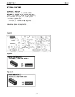
Internal Controls Description
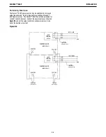
The User Interface pc board has one bank of dip switches
(See Figure A.1).
As shipped from the factory and under normal
conditions, the dip switches are all in the ‘off’ position
(Figure A.2).
There are 2 instances that require a change of the dip switch.
1. Enter VRD Mode (VRD Enabled)
a. Turn switch #5 to the ‘ON’ Position
(See Figure A.3).
Dip Switch Location on User Interface PCB
-HJ[VY`+LMH\S[:L[[PUN
(SS:^P[JOLZPU[OLº6--»7VZP[PVU
65
6--
=9+,UHISLK :L[[PUN
:^P[JOPU[OLº65»7VZP[PVU
65
6--
Figure A.1
Figure A.2
Figure A.3