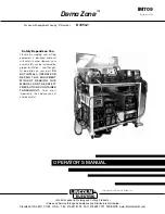
Lincoln Electric Demo Zone Operator'S Manual Download Page 10

A-3

INSTALLATION   

DEMO ZONE

A-3

INSTALLATION OF FIELD INSTALLED
OPTIONS

CASTER WHEELS (PART OF K1848-1)

Caster wheels, which are provided, can be installed
by lifting the Demo Zone approximately eight inches
above ground level. Use the mounting hardware sup-
plied to fasten the caster wheel to the mounting plate.
Tighten all fasteners. 

INSTALLATION OF EQUIPMENT
REQUIRED FOR RECOMMENDED
PROCESSES

1. As shipped from the factory, two diagonal braces

are bolted to either side of the Demo Zone. The
braces are approximately 62" in length.

• Remove the brace on the tool box side of the Demo Zone
• Do not remove the brace located on the Ranger

250 side of the Demo Zone.

2. The Demo Zone is made for ease of set up. Drive

rolls are installed and liners are in the guns. 

3. A Harris Kit, containing gas components, is includ-

ed with the Demo Zone. Some details about the kit: 

• The double flow meter-regulator is for the argon

gas cylinder. A "Y" fitting is also used on one of the
flow meter outlets. The argon is fed to the Spool
Gun, The Square Wave TIG 175 and the two-piece
TIG torch attached to the Ranger 250.

• The other regulator is provided for the 75/25

argon/CO2 gas cylinder. Connect a "Y" fitting to this
regulator. The Power MIG and LN25 is fed from the
"Y" fitting. Use hoses with inert gas fittings. The
short hose is used with the LN7.

• The oxygen fitting (with 1/4 inch pipe thread) is for

use with the Pro-Cut gas hose. Use the short oxy-
gen hose between the Pro-Cut and regulator. 

4. Two plasma torches are provided with the Demo

Zone. Use the short length plasma torch with the
Demo Zone. The torch with the long length is not
recommended because the length is inconvenient
when used with the Demo Zone. Store the long
plasma torch. Use the long torch if the Pro Cut is
removed from the Demo Zone.  

5. BEFORE the gas cylinders are installed, run the

gun for the Power MIG from the back of the rack
through the bench (under) and then up to the
Power MIG. This gun will run along the back of the
Square Wave TIG 175 and then to a gun holder. It
should be long enough to reach the worktable and
this helps keep the cables from getting tangled.

6. BEFORE the gas cylinders are installed, measure

the cable length needed for the spool gun (it is rout-
ed the same way as the Power MIG gun) and coil
the rest, wire tie it and store it underneath the
bench between the Ranger and Power MIG.

7. BEFORE the gas cylinders are installed, connect

the battery in the Ranger 250.

8. Gas cylinder covers will improve the appearance of

your unit. When used, put the covers on before
installing the cylinder.

9. Place the cylinders in the Demo Zone. The cylin-

ders can be installed by using the rear or side
openings, or a combination of both. 

When using the rear frame opening, move the upper
and lower support bars out of way. Install the cylin-
ders and replace the support bars to the closed
position.

When using side frame opening, lift brace and swing
out of the way. Install the cylinders and swing brace
back into position, push brace down through locking
tube to secure. 

Place the air cylinder directly in back of the Pro Cut.
Place the argon cylinder next to the air cylinder.

10. Install the optional casters. This is easily done

after placing cylinders in Demo Zone, as the
height of the Demo Zone is higher with the wheels
installed.

11. Set up the two TIG torches provided. The TIG

torch that comes with the SW175 is used on both
AC and DC. A recommendation is to use a point at
one end of the tungsten and a ball at the other
end. 

12. The welding table must exposed before demon-

strating. Pull the table to the open position when in
use. The table can be pushed back in, out of the
way, when the table is not in use. Since the table
has a bolted work lead permanently attached, no
work clamp is necessary for welding or cutting
operations. 

Summary of Contents for Demo Zone

Page 1: ...INSTALL OPERATE OR REPAIR THIS EQUIPMENT WITHOUT READING THIS MANUAL AND THE SAFETY PRECAUTIONS CONTAINED THROUGHOUT And most importantly think before you act and be careful For use with equipment ha...

Page 2: ...ERS SHOULD CONSULT WITH THEIR DOCTOR BEFORE OPERATING Read and understand the following safety highlights For additional safety information it is strongly recommended that you purchase a copy of Safet...

Page 3: ...arth ground 3 f Maintain the electrode holder work clamp welding cable and welding machine in good safe operating condition Replace damaged insulation 3 g Never dip the electrode in water for cooling...

Page 4: ...the welding sparks from starting a fire Remember that welding sparks and hot materials from welding can easily go through small cracks and openings to adjacent areas Avoid welding near hydraulic lines...

Page 5: ...t non inflammables 4 Des gouttes de laitier en fusion sont mises de l arc de soudage Se prot ger avec des v tements de protection libres de l huile tels que les gants en cuir chemise paisse pan talons...

Page 6: ...to be applied to each is explained below WARNING This statement appears where the information must be followed exactly to avoid serious personal injury or loss of life This statement appears where th...

Page 7: ...ment B 1 Recommended Processes B 1 Process Limitations B 1 Recommended Equipment Interface B 2 Equipment Limitations B 2 Design Features B 2 Platform Commonalities B 2 Operational Controls and Feature...

Page 8: ...67 lbs with gas cylinders 1346 2 mm 1676 4 mm 1346 2 mm 774 3 kg w o gas cylinders 1119 0 kg with gas cylinders The Demo Zone is intended for display and demonstration use It is intended for light dut...

Page 9: ...high frequency unit of the Square Wave TIG 175 is used OUTPUT CABLES AND CONNECTIONS ELECTRODE AND WORK CABLE CON NECTIONS The Demo Zone is supplied with the output cables connected at the power sour...

Page 10: ...gas cylinders are installed run the gun for the Power MIG from the back of the rack through the bench under and then up to the Power MIG This gun will run along the back of the Square Wave TIG 175 and...

Page 11: ...flat surface The Demo Zone is intended for indoor use only The Demo Zone must be sheltered from rain and water ENGINE EXHAUST Provide an exhaust capability for the Ranger 250 machine Flexible metal ex...

Page 12: ...ECOMMENDED PROCESSES The Demo Zone is capable of demonstrating MIG TIG SMAW CAC and plasma cutting PROCESS LIMITATIONS determined by individual equipment DEMO ZONE ELECTRIC SHOCK can kill Do not touch...

Page 13: ...epta cle Locate the circuit breaker at the rear of the Demo Zone and switch it on Plug the lighting system into a 120 volt receptacle Switch the power for individual machines on as required for demons...

Page 14: ...duty cycles of the Demo Zone are given If the duty cycle or input currents exceed the capability of the 40 amp circuit breaker the breaker will trip off For lower output currents the duty cycle is ext...

Page 15: ...OPTIONS ACCESSORIES none FIELD INSTALLED OPTIONS ACCESSORIES CASTER WHEELS Caster wheels which are provided are a field installed option for the Demo Zone The 5 inch diame ter caster wheels offer hig...

Page 16: ...or punctures in the cable jacket or any condition that would affect the proper opera tion Inspect gas hoses and regulators Inspect gas cylinder chains and fasteners The weld table is insulated from t...

Page 17: ...performed by Lincoln Electric Factory Trained Personnel Unauthorized repairs performed on this equipment may result in danger to the technician and machine operator For your safety and to avoid Elect...

Page 18: ...OR GAS AND OIL RESISTANT 600 V UL B W 230 VOLT INPUT 50 AMP RECEPTACLE 50 AMP RECEPTACLE 50 AMP RECEPTACLE 50 AMP RECEPTACLE G TO GROUND PER NATIONAL ELECTRIC CODE N A BOX BONDED TO GROUND WORK CIRCUI...

Page 19: ...NOTES DEMO ZONE...

Page 20: ...electrically live parts or electrode with skin or wet clothing Insulate yourself from work and ground No toque las partes o los electrodos bajo carga con la piel o ropa moja da Aislese del trabajo y...

Page 21: ...e Be und Entl ftung des Arbeitsplatzes Mantenha seu rosto da fuma a Use ventila o e exhaust o para remover fumo da zona respirat ria Turn power off before servicing Desconectar el cable de ali mentaci...

Page 22: ...and Service through Subsidiaries and Distributors Worldwide Cleveland Ohio 44117 1199 U S A TEL 216 481 8100 FAX 216 486 1751 WEB SITE www lincolnelectric com World s Leader in Welding and Cutting Pr...

Reviews: