Lincoln Electric COBRAMAX IM774 Operator'S Manual Download Page 12

CobraMAX™ Owner's Manual - 

Page 2

Gas Hose

The gas hose is secured over the barbed gas fitting with a tie wrap.  The 

cabinet end of the gas hose uses our standard gas fitting (1/8” - 27 nps).

Water Hose

If so equipped, one end of the water hose is secured over the barbed water 

fitting with a tie wrap and the other end is connected to the center fitting on 

the power block.

Electric Cable

A seven conductor control cable is used on the CobraMAX

 gun.  The gun 

end of the control cable is secured to the gun with a boot clamp and soldered 

to the pot assembly, tirgger and water leads.  Slack is left in the electric cable 

as it exits the back of the gun to prevent cable breakage.  The cabinet end 

has a seven pin “W” clocked amphenol connector.

Section B   

Operation

General

The CobraMAX

 gun maintains a constant, steady, uniform wire feed speed, 

regardless of curved or looped wire conduit.  The constant push exerted 

by the slave motor in the cabinet, combined with the pull of the gun motor, 

causes the wire to literally float friction-free through the wire conduit.  The 

24VDC gun motor is controlled by a three and three-quarter (3 3/4) turn 

potentiometer in the gun handle.

Controls and Settings

Potentiometer

The laterally-positioned potentiometer is located in the lower end of the 

handle, providing  up to 800 ipm with 3 3/4 turns.

Micro Switch

The micro switch assembly consists of the micro switch and leads. 
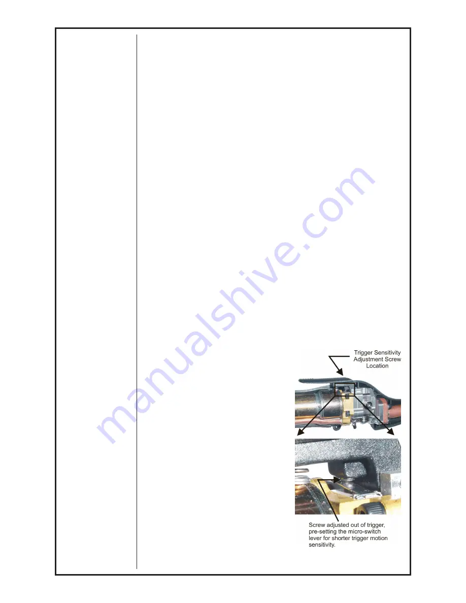
Trigger Sensitivity


The amount of trigger level travel can 

be shortened for a "quicker" or "more 

responsive" action. 
A more sensitive trigger lever is 

produced by reducing the gap between 

the trigger lever and the micro switch 

lever. By turning-in the trigger sensitivity 

adjustment screw, it closed the gap 

between the trigger lever and the micro 

switch lever.
This will enable the operator to increase 

the sensitivity of the trigger lever. 

Sensitivity Adjustment

With the wire feeder turned on (with 

or without welding wire loaded), turn 

the screw in until the micro-switch is 

activated. Once activated, the tortch and 

wire feeder motors will begin feeding 

wire. Retract the screw accordingly until 

the system is deactivated and adjusted to 

the operators' liking.

Summary of Contents for COBRAMAX IM774

Page 1: ...part DO NOT INSTALL OPERATE OR REPAIR THIS EQUIPMENT WITHOUT READING THIS MANUAL AND THE SAFETY PRECAUTIONS CONTAINED THROUGHOUT And most importantly think before you act and be careful OPERATOR S MA...

Page 2: ......

Page 3: ...General 2 Controls and Settings 2 Drive Roll and Idler Rolls 3 Accessories Section C Optional Kits 4 Conduits 4 Snake Skins 4 Contact Tips 5 Gas Cups 5 Maintenance Section D Periodic Maintenance 6 Mai...

Page 4: ...C Electromagnetic Compatibility EMC Directive 89 336 EEC Standards Arc Welding Equipment Part I Welding Power Sources IEC 60974 1 September 1998 Second Edition Arc Welding Equipment Wirefeed Systems I...

Page 5: ...CobraMAX Owner s Manual Page...

Page 6: ...water for cooling 3 h Never simultaneously touch electrically hot parts of electrode holders connected to two welders because voltage between the two can be the total of the open circuit voltage of bo...

Page 7: ...n easily go through small cracks and openings to adjacent areas Avoid welding near hydraulic lines Have a fire extinguisher readily available 6 b Where compressed gases are to be used at the job site...

Page 8: ...CobraMAX Owner s Manual Page iv...

Page 9: ...CobraMAX Owner s Manual Page...

Page 10: ...pecially important when identifying the correct replacement parts On Line Product Registration Register your machine with Lincoln Electric either via fax or over the Internet For faxing Complete the f...

Page 11: ...ass or aluminum or create a custom mix using this formula Use 3 Gallons 11 4 Liters Distilled water Use 1 Gallon 3 8 Liters ethylene glycol Use 1 tsp 5 ml liquid glycerin The Coolant rate should be 1...

Page 12: ...uses the wire to literally float friction free through the wire conduit The 24VDC gun motor is controlled by a three and three quarter 3 3 4 turn potentiometer in the gun handle Controls and Settings...

Page 13: ...the pressure against the drive roll as shown in Figure 1 2 Align the drive roll removal tool P N 931 0100 over the flats of the drive roll as shown in Figure 2 Hold the gun with one hand or on a tabl...

Page 14: ...roll assy Insulated Groove Drive Roll Kit KP1594 1 16 005 0644 For 062 1 6mm dia aluminum wire Includes insulated groove drive roll and idler insulated roll assy Replacement Kits Handle Kit 005 0700...

Page 15: ...P N No 6 3 8 9 5mm 621 0420 KP2249 1 No 8 1 2 15 8mm 621 0421 KP2250 1 No 10 5 8 15 8mm 621 0422 KP2251 1 standard furnished with gun Gas Cups Spring Loaded Contact Tip 3 8 Diameter Wire Size Tip ID A...

Page 16: ...If repairs do become necessary qualified shop maintenance personnel can easily replace any part Recommended Spare Parts List Qty Part No Description 1 LE KP2072 30 MK 615 0601 15 Conduit 15 ft 1 LE KP...

Page 17: ...owners manual for speed control operation Wire feeds but welding wire is not energized Loose or no cable connections Check all power connections Contactor control cable loose or in wrong position Che...

Page 18: ...o switch in the gun activates both the slave motor and gun motor circuits in the cabinet Therefore if the slave motor and brake solenoid operate but the gun does not look more toward the gun motor s 2...

Page 19: ...er s Manual Page Section F Appendices Diagrams Parts List 001 1420 CobraMAX Exploded View 12 003 2141 Front Body Assembly 14 Ultra Flex Air Cooled Lead Assembly 15 Water Cooled Lead Assembly 16 Wiring...

Page 20: ...d View Items 25 and 44 not shown for clarity Apply item 49 to contact surfaces Apply item 48 before installing Apply item 45 to contact surfaces Apply item 46 to Threads Apply item 47 to Threads Apply...

Page 21: ...Door Molded Python 12 1 303 0540 O Ring 426 ID x 07 W 38 1 005 0700 Handle Kit includes line items 18 31 34 and 37 13 2 319 0254 Screw FH Phil 82 4 40 x 3 8 SST 39 14 1 319 0258 Screw FH Phil 82 4 40...

Page 22: ...tion 1 Not Available Separately 2 Not Available Separately 3 1 325 0206 SCR Ph 10 24 3 8 4 1 333 0082 Washer Lock 10 5 1 419 0092 Spring Comp 0 31 OD x 0 20 ID 6 1 421 0525 Pin Dowel 1 8 x 7 8 Sst 7 1...

Page 23: ...but must be removed from this end when used on the CobraMAX 227 Series Ultra Flex Cable Assemblies Length Conduit Power Cable Electrical Cable Gas Hose Snake Skin 15 4 5m 615 0601 15 001 2527 005 069...

Page 24: ...is end when used on the CobraMAX torque requires 100 5 in lb 228 Series Ultra Flex Cable Assemblies Length Conduit 4 Power Water Cable Electrical Cable Gas Hose Water Hose Snake Skin 15 4 5m 615 0601...

Page 25: ...ol Connector Viewed from front of connector E C A B D G F TORCH MOTOR TORCH POT TOR CH TRIGGER 5K Red Red Black Black Blue Blue Yellow Yellow Brown Brown White White Green Green 1 3 2 Cabinet End Amph...

Page 26: ...CobraMAX Owner s Manual Page 16...

Page 27: ...CobraMAX Owner s Manual Page 17...

Page 28: ...Spool Guns Python CobraMAX Cobra SX Cobra MX 1 year 3 Sidewinder Spool Gun Prince SG Spool Guns Modules 180 days 4 Repairs Exchanges Parts 90 days Classification of any item into the foregoing catego...

Reviews: