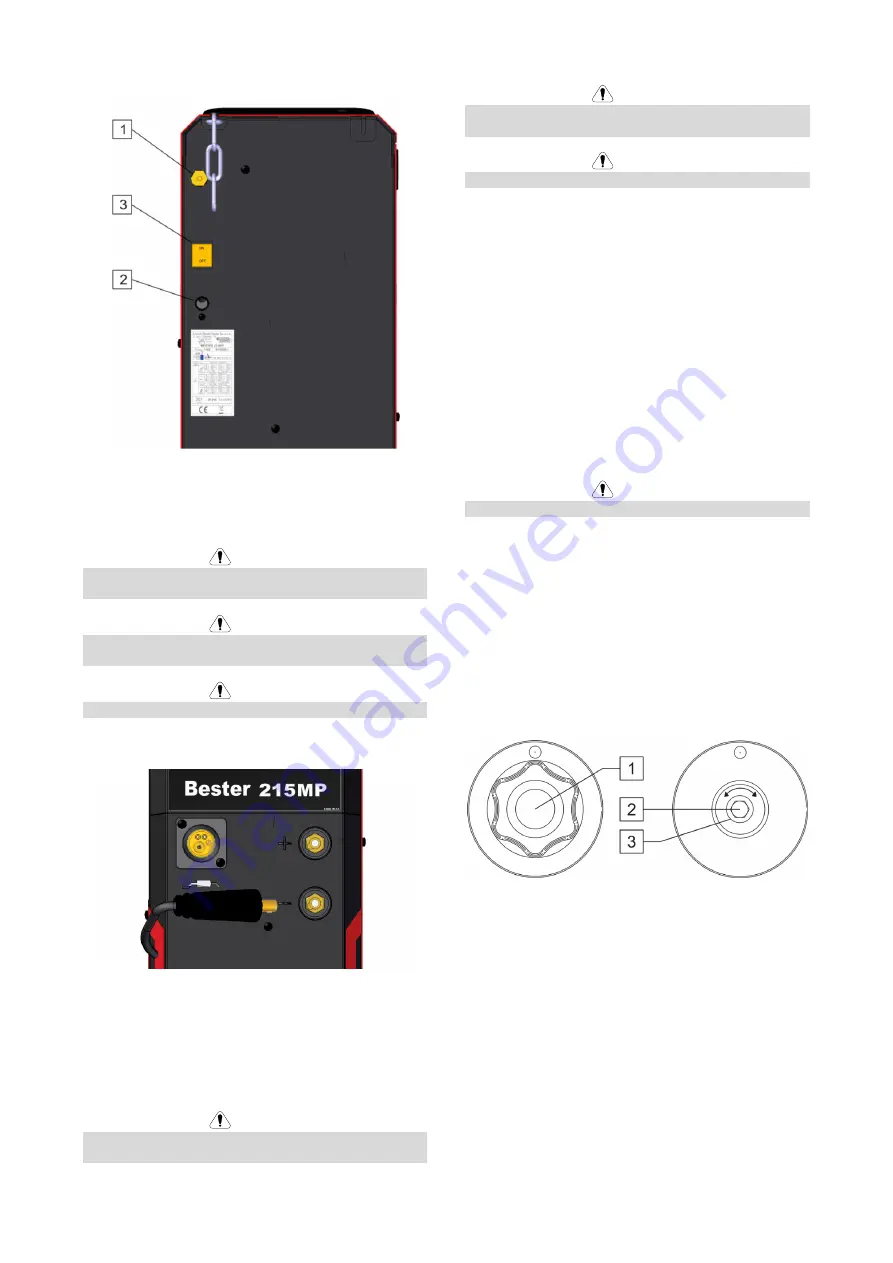
Lincoln Electric B18260-1 Operator'S Manual Download Page 12


English 

10 

English 

Rear Panel 


Figure 3 


1.  Gas connector 

2.  Input power cord 

3.  Power switch 


 WARNING


When the machine is switched again on, last welding 

process will be recalled. 


 WARNING


If the push-button is pushed in MIG process in, the output 

terminals will lived. 


 WARNING


During MMA process, the output terminals are still lived. 


The installation and connection 


Figure 4 


If the welding polarity has to be changed, user should: 

  Switch off the machine. 

  Determine the polarity for the electrode to be used 

(or wire). Consult the data for this information. 

  Select and set the correct polarity: positive (terminal 

8) or negative (terminal 9) 


 WARNING


Before welding check the polarity for using electrodes and 

wires. 

 WARNING


The machine must be used with the door completely 

closed during welding. 


 WARNING


Not use handle to move the machine during work. 


Loading the Electrode Wire 

  Turn the machine off. 

  Open the side cover of the machine. 

  Unscrew the locking nut of the sleeve. 

  Load the spool with the wire on the sleeve such that 

the spool turns  anticlockwise when the wire is fed 

into the wire feeder. 

  Make sure that the spool locating pin goes into the 

fitting hole on the spool. 

  Screw in the fastening cap of the sleeve. 

  Put on the wire roll using the correct groove 

corresponding to the wire diameter. 

  Free the end of the wire and cut off the bent end 

making sure it has no burr. 

  The device is adapted to the spool max. 15 kg  

300 mm 


 WARNING


Sharp end of the wire can hurt. 


  Rotate the wire spool anticlockwise and thread the 

end of the wire into the wire feeder as far as the Euro 

socket. 

  Adjust force of pressure roll of the wire feeder 

properly. 


Adjustments of Brake Torque of Sleeve 

To avoid spontaneous unrolling of the welding wire the 

sleeve is fitted with a brake. 

Adjustment is carried by rotation of its Allen screw M8, 

which is placed inside of the sleeve frame after 

unscrewing the fastening cap of the sleeve. 


Figure 5 


1.  Fastening cap. 

2.  Adjusting Allen screw M8. 

3.  Pressing spring. 


Turning the Allen screw M8 anticlockwise increases the 

spring tension and you can increase the brake torque 


Turning the Allen screw M8 clockwise decreases the 

spring tension and you can decrease the brake torque. 


After finishing of adjustment, you should screw in the 

fastening cap again. 


Summary of Contents for B18260-1

Page 1: ...IM3131 07 2020 REV01 BESTER 215MP OPERATOR S MANUAL ENGLISH Lincoln Electric Bester Sp z o o Jana III Sobieskiego 19A 58 263 Bielawa Poland ww lincolnelectric eu...

Page 2: ...he table below your equipment identification information Model Name Code Serial Number can be found on the machine rating plate Model Name Code Serial Number Date Where Purchased ENGLISH INDEX Technic...

Page 3: ...rrent Range Welding Voltage Range MIG U0 90V 30A 200A 15 5V 24 0V FCAW SS U0 90V 30A 200A 15 5V 24 0V MMA U0 90V 15A 180A 20 6V 27 2V TIG U0 90V 15A 180A 10 6V 17 2V OTHER PARAMETERS Power Factor Prot...

Page 4: ...des Welding time in seconds D16 16A slow blow 2 0 60 70 10 Continuous work D16 16A slow blow 2 5 85 90 10 Continuous work D16 16A slow blow 3 2 120 125 6 450 D16 16A slow blow 4 0 130 145 Half of elec...

Page 5: ...G mode STICK mode After 30 minutes of non working Fan off The value of efficiency and consumption in idle state have been measured by method and conditions defined in the product standard EN 60974 1 2...

Page 6: ...process gas usage depends on cross sectional area of the nozzle For comonnly used torches Helium 14 24 l min Argon 7 16 l min Notice Excessive flow rates causes turbulence in the gas stream which may...

Page 7: ...ke pacemakers and hearing aids Check the electromagnetic immunity for equipment operating in or near the work area The operator must be sure that all equipment in the area is compatible This may requi...

Page 8: ...AGNETIC FIELDS MAY BE DANGEROUS Electric current flowing through any conductor creates electric and magnetic fields EMF EMF fields may interfere with some pacemakers and welders having a pacemaker sha...

Page 9: ...lding process including sparks and heat sources CYLINDER can be fasten on the machine s shelf but the height of gas cylinder doesn t have to be higher than 1 1m The gas cylinder which is fastened on t...

Page 10: ...l operation may adversely affect the operation of nearby radio controlled machinery which may result in injury or equipment damage Read the section on electromagnetic compatibility in this manual Do n...

Page 11: ...ll come on if the duty cycle is exceeded It shows that the inner temperature is over the permitted level the machine should be stopped being used to allow it cool down Welding can continue after the p...

Page 12: ...iclockwise when the wire is fed into the wire feeder Make sure that the spool locating pin goes into the fitting hole on the spool Screw in the fastening cap of the sleeve Put on the wire roll using t...

Page 13: ...the input power OFF Release the pressure roll lever 1 Unscrew the fastening cap 2 Change the drive roll 3 with the compatible ones corresponding to the used wire WARNING Be sure that the gun liner and...

Page 14: ...older with lead to MMA 9 Work lead 8 Connect the work lead to the welding piece with the work clamp Install the proper electrode in the electrode holder Turn the welding machine on Set welding mode to...

Page 15: ...be disconnected from the machine before each maintenance and service After each repair perform proper tests to ensure safety Customer Assistance Policy The business of The Lincoln Electric Company is...

Page 16: ...nnected Check the connection 4 Arc is not stable and spatter is large Too large contact tip makes the current unsteady Change to proper contact tip and or drive roll Too thin power cable makes the pow...

Page 17: ...ces of Very High Concern for Authorisation of REACh Your particular product may contain one or more of the listed substances Instructions for safe use use according to Manufacturer instructions wash h...

Page 18: ...25 1 08R Adapter for spool S200 200mm K10158 1 Adapter for spool type B300 K10158 Adapter for spool type S300 W10529 17 4V TIG torch WTT2 17 4m with valve E H 200A 25 3M Welding cable with electrode h...

Reviews: