Lincoln Electric 9535 Operator'S Manual Download Page 14

E-2

TROUBLESHOOTING

E-2

IDEALARC R3R 375-I, 500-I AND 600-I

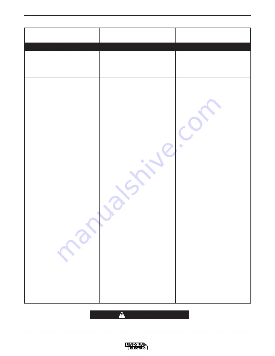
Observe all Safety Guidelines detailed througout this manual

If for any reason you do not understand the test procedures or are unable to perform the tests/repairs safely, contact your

Local

Lincoln Authorized Field Service Facility

for technical troubleshooting assistance before you proceed.

CAUTION

FUNCTION PROBLEMS

PROBLEMS

(SYMPTOMS)

POSSIBLE CAUSE

RECOMMENDED

COURSE OF ACTION

A. Input contactor chatters.

B. Machine input contactor does not

operate.

1.Faulty input contactor.

2.Low line voltage.

1.Supply line fuse blown.

2.Power circuit dead.

3.Broken or loose power lead.

4.Wrong voltage.

5.Thermostats tripped. (High

Temperature Warning Light
should be lit.) (Welder
overheated.)

6.Input contactor coil open.

7.Open winding on 115V pilot

transformer.

8.Power ON-OFF switch not

closing.

9.Lead broken or loose connec-

tion in 115V starter circuit.

10.Thermostats defective. (High

Temperature Warning Light
should be lit.)

1.Repair or replace.

2.Check with Power Company.

1.Replace (look for reason for

blown fuse first).

2.Check voltage.

3.Repair.

4.Check voltage against

instructions.

5.a. Make sure the fan is operating

and that there are no obstruc-
tions to free flow of air.

b. Operate at normal current

and duty cycle.

c. Replace High Temperature

Warning Light if defective.

6.Replace.

7.Replace.

8.Replace.

9.Replace.

10.Turn input power off (115V cir-

cuit is hot when input power is
connected). Check thermostats
with continuity meter – should
read short-circuit when machine
is cool. Replace if defective.
There are two thermostats; one
on the secondary lead and one
on the choke. Replace High
Temperature Warning Light if
defective.

Summary of Contents for 9535

Page 1: ...part DO NOT INSTALL OPERATE OR REPAIR THIS EQUIPMENT WITHOUT READ ING THIS MANUAL AND THE SAFETY PRECAUTIONS CON TAINED THROUGHOUT And most importantly think before you act and be careful For use wit...

Page 2: ...R WEARERS SHOULD CONSULT WITH THEIR DOCTOR BEFORE OPERATING Read and understand the following safety highlights For additional safety information it is strongly recommended that you purchase a copy of...

Page 3: ...ical earth ground 3 f Maintain the electrode holder work clamp welding cable and welding machine in good safe operating condition Replace damaged insulation 3 g Never dip the electrode in water for co...

Page 4: ...cover them to prevent the welding sparks from starting a fire Remember that welding sparks and hot materials from welding can easily go through small cracks and openings to adjacent areas Avoid weldi...

Page 5: ...appropri s et non inflammables 4 Des gouttes de laitier en fusion sont mises de l arc de soudage Se prot ger avec des v tements de protection libres de l huile tels que les gants en cuir chemise pais...

Page 6: ...ion below for future reference This information can be found on your machine nameplate Product _________________________________________________________________________________ Model Number __________...

Page 7: ...lation Section A Input Power Connection A 1 Duty Cycle A 1 Output Connections A 1 Operating Instructions Section B Accessories Section C Maintenance Section D Troubleshooting Section E Troubleshooting...

Page 8: ...ound lead to the ground stud marked with the symbol Install the reconnect panel for the proper input voltage per the diagram pasted inside the access panel cover DUTY CYCLE The maximum output rating o...

Page 9: ...ol dial labeled I on the front of the machine indicates the output current On the R3R 375 I there is only one dial On the R3R 500 I and 600 I there are two dials The A range controls the current over...

Page 10: ...WITCH Remote Output Current Control F POLARITY SWITCH Factory installed option on domestic models only Electrode Polarity Positive Electrode Polarity Negative Do Not Switch While Welding G RATING PLAT...

Page 11: ...ROL AND K870 FOOT AMPTROL Connect directly to the 6 pin Amphenol on the front of the power source POCKET AMPTROL factory installed only The Pocket Amptrol option provides a remote current control for...

Page 12: ...required The probe tip should be kept in condition to provide sharp edges at the ends to assure penetration of heavy oxide coatings on the work piece A blunted tip could result in giving different wel...

Page 13: ...i ties that may contribute to the machine symptom Step 3 RECOMMENDED COURSE OF ACTION This column provides a course of action for the Possible Cause If you do not understand or are unable to perform t...

Page 14: ...ed 6 Input contactor coil open 7 Open winding on 115V pilot transformer 8 Power ON OFF switch not closing 9 Lead broken or loose connec tion in 115V starter circuit 10 Thermostats defective High Tempe...

Page 15: ...Electrode or work lead loose or broken 2 Open transformer primary or secondary circuit 3 Supply line fuse blown 4 Input line grounded causing single phase input 5 Input leads not connected to contact...

Page 16: ...Troubleshooting Section E 1 Input fuse blown Machine is single phased 2 One phase of main transformer windings open 3 Defective power bridge 1 Improper ventilation 2 Loaded beyond rating 3 Fan inoper...

Page 17: ...baffle 1 Poor work or electrode cable connection 2 Current too low 3 Welding leads too small 4 Open SCR or diode in power rectifier bridge 5 Control circuit problems 1 Input contactor contacts frozen...

Page 18: ...COURSE OF ACTION L Optional remote current control not functioning See Troubleshooting Section C before connecting 1 Current control switch in the wrong position 2 Leads 75 76 and 77 not con nected t...

Page 19: ...ng and replacing check repair are OK one at a time changes OCV each gate lead one at a time does NOT change OCV Codes below 9500 with power off remove leads from Identify gate lead that when Codes abo...

Page 20: ...rent control rheostat or the control circuit Only the green lead can and should be grounded to the machine case When extending the standard remote control make sure the leads are the same and the spli...

Page 21: ...crew Reading should be infinite 5 If either step 3 or step 4 fails replace the switch I REMOTE CONTROL CHECK For codes above 9500 the remote control Amphenol pin assignments are pin C 75 pin B 76 and...

Page 22: ...d a much higher resistance in Step c K POWER SILICON CONTROLLED REC TIFIER TEST The SCR must be mounted in the heat sink when making this test a Connect the ohmmeter set to the X10 scale leads to the...

Page 23: ...208 209 224 OPTIONAL METER KIT VM AM FRAME GROUND 217 217 A A 115 V 201 202 203 7 S S 10 1 4 5 6 66V BOTTOM PRIMARY TOP PRIMARY T1 X1 X2 X3 SEC SEC SEC 16 17 18 ARE PRESENT ON 380 500 OR 460 575 MACH...

Page 24: ...375 I 500 I AND 600 I F 2 NOTE This diagram is for reference only It may not be accurate for all machines covered by this manual The specific diagram for a particular code is pasted inside the machin...

Page 25: ...RING DIAGRAMS IDEALARC R3R 375 I 500 I AND 600 I F 3 R3R 375 I 500 I and 600 I K817 or K817R K841 not shown Part No Type A B C D F G H M12244 7 R3R 32 00 15 39 3092 1 44 30 02 11 33 07 06 94 M12244 7...

Page 26: ...NOTES IDEALARC R3R 375 I 500 I AND 600 I...

Page 27: ...NOTES IDEALARC R3R 375 I 500 I AND 600 I...

Page 28: ...NOTES IDEALARC R3R 375 I 500 I AND 600 I...

Page 29: ...NOTES IDEALARC R3R 375 I 500 I AND 600 I...

Page 30: ...CHTEN Do not touch electrically live parts or electrode with skin or wet clothing Insulate yourself from work and ground No toque las partes o los electrodos bajo carga con la piel o ropa moja da Aisl...

Page 31: ...Sorgen Sie f r gute Be und Entl ftung des Arbeitsplatzes Mantenha seu rosto da fuma a Use ventila o e exhaust o para remover fumo da zona respirat ria Turn power off before servicing Desconectar el ca...

Page 32: ...and Service through Subsidiaries and Distributors Worldwide Cleveland Ohio 44117 1199 U S A TEL 216 481 8100 FAX 216 486 1751 WEB SITE www lincolnelectric com World s Leader in Welding and Cutting Pr...

Reviews: