


A-2
INSTALLATION
A-2
DURAWELD
TM
350/500
SAFETY PRECAUTIONS
Read the entire installation section before starting
installation.
ELECTRIC SHOCK can kill.
Only qualified personnel
should perform this installation.
Turn the input power OFF
at the main switch or fuse box
before working on this
equipment. Turn off the input power to any other
equipment connected to the welding system at
the main switch or fuse box before working on
the equipment.
Do not touch electrically “Hot” parts.
Always connect the DURAWELD
TM
grounding lug
(located at the rear of the case) to a proper safety
(Earth) ground.
DURAWELD
TM
must only be used on three-
phase, MEN input power.
SELECT SUITABLE LOCATION
This power source should not be subjected to rain, nor
should any parts of it be submerged in water. Doing so
may cause improper operation as well as pose a safety
hazard. The best practice is to keep the machine in a
dry, sheltered area.
The bottom of machine must always be placed on a
firm, secure, level surface. There is a danger of the
machine toppling over if this precaution is not
taken.
Place the welder where clean cool air can freely
circulate in through the side and back louvers and out
through the case bottom. Water dust or any foreign
material that can be drawn into the welder should be
kept a minimum. Failure to observe these precautions
can result in excessive operating temperatures and
nuisance shutdowns.
Locate the DURAWELD
TM
machine away from radio
controlled machinery. Normal operation of the welder
may adversely affect the operation of RF controlled
equipment, which may result in bodily injury or damage
to the equipment.
INPUT POWER AND GROUNDING
CONNECTION
Only a qualified electrician should connect the
input leads to the DURAWELD
TM
. Connections
should be made in accordance with the connection
diagram. Failure to do so may result in bodily injury
or death.
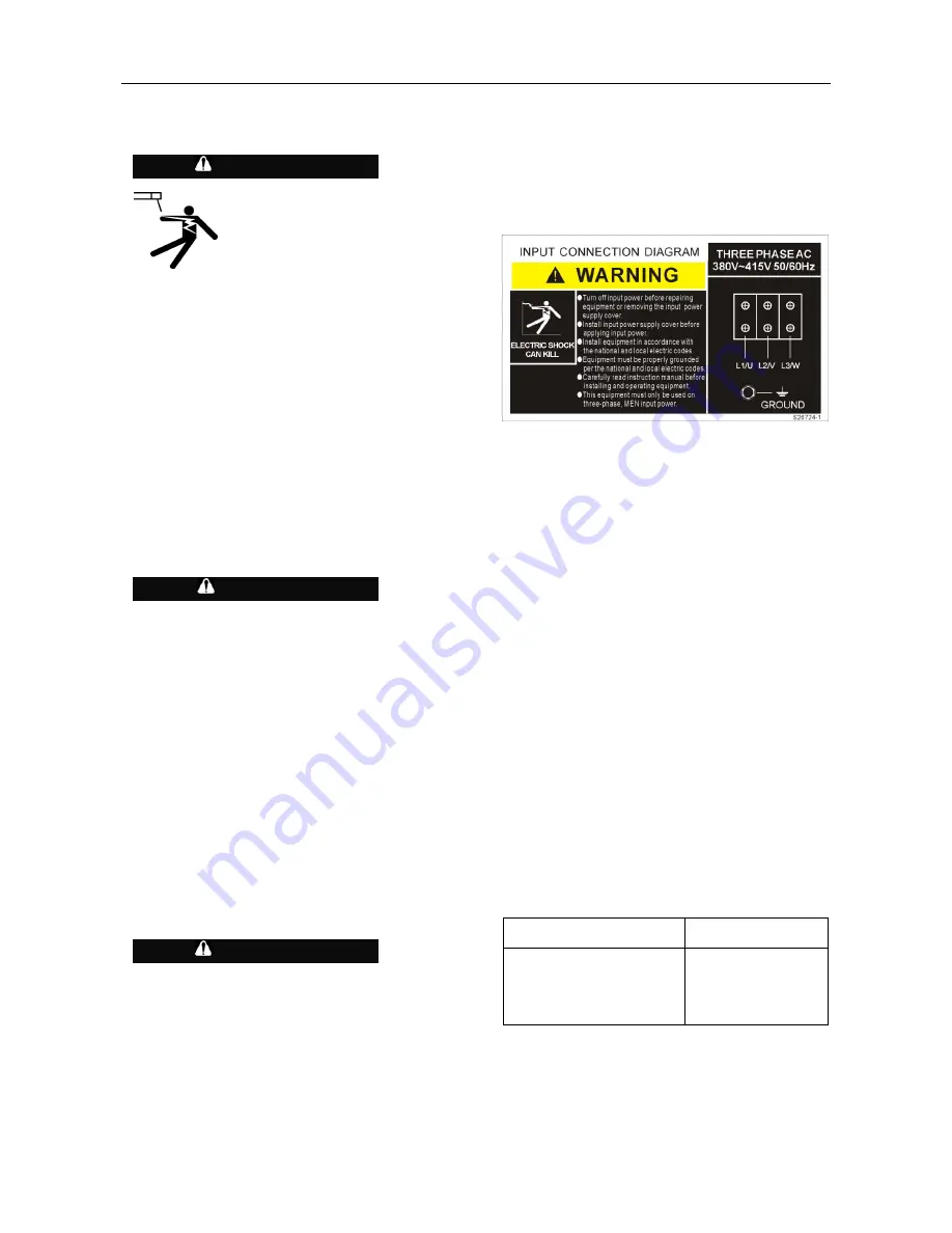
Open the input box on the rear of the case. Use a
three-phase supply line, the three live wires should go
through the three holes of the input wire holder and be
securely clamped and fixed. Connect L1, L2, L3 and
ground according to the Input Supply Connection
Diagram decal, refer to Figure A.1 on this page.
FIGURE A.1 – Input Supply Connection Diagram
The DURAWELD
TM
is supplied connected for 50Hz
input. In regions where the frequency of electricity is
60HZ, the DURAWELD
TM
machine can identify the 60
HZ frequency automatically and work in terms of this
frequency.
Make sure the amount of power available from the input
connection is adequate for normal operation of the
machine. Refer to the Technical Specifications at the
beginning of this Installation section for recommended
fuse and wire sizes. Fuse the input circuit with the
recommended super lag fuse or delay type breakers.
Using fuses or circuit breakers smaller than
recommended may result in “nuisance” shut-offs from
welder inrush currents, even if the machine is not being
used at high currents.
OUTPUT AND WIRE FEEDER
CONNECTIONS
Connect a work lead of sufficient size and length (Per
Table A.1) between the Negative Output terminal on the
power source and the work. Be sure the connection to
the work makes tight metal-to-metal electrical contact.
To avoid interference problems with other equipment
and to achieve the best possible operation, route all
cables directly to the work and wire feeder. Avoid
excessive lengths and do not coil excess cable.
Minimum work and electrode cable sizes are as follows:
TABLE A.1
Current (60% Duty Cycle)
Minimum Copper
Work Cable Size
200A
300A
400A
500A
Up To 30m Length
30 mm
2
50 mm
2
70 mm
2
95 mm
2
Note: Recommended cable sizes may vary due to
different cable quality. The overall voltage pressure of
grounding and welding cables is no more than 4V under
rated current.
WARNING
CAUTION
WARNING