background image

LDT10

EXAMPLE

Let's suppose that the actuator is installed on a 5-mm pitch worm screw. If you
set 

Pulse per revolution

 = 500 and 

Decimals

 = 2, at each rotation of the screw

the system performs a 5-mm pitch with a resolution of one hundredth of a
millimetre.

WARNING

As   the   setting   of   the   decimal   digits   directly   affects   the   calculation   of   the
actuator's position, after confirming a new value please check and, if necessary,
recalculate the target positions in all recipes.

Backlash direction

This parameter allows to enable the 

unidirectional positioning function

. The

unidirectional positioning function (backlash compensation) has to be used to
compensate for (minimize) the effects of the backlash, i.e. the 

clearance or lost

motion   in   the   mechanism   caused   by   gaps   between   the   parts.

  As   it   is

unidirectional, this parameter further allows to set whether the compensation is
performed when the axle moves forwards (positive direction) or when it moves
backwards (negative direction).
If 

OFF

 is set in this option, the function is disabled.

If 

POSITIVE

 is set in this option, the backlash compensation is performed only

when the axle moves toward positive target by applying the value set in the
next 

Backlash step length

 item.

If 

NEGATIVE

 is set in this option, the backlash compensation is performed only

when the axle moves toward negative target by applying the value set in the
next 

Backlash step length

 item.

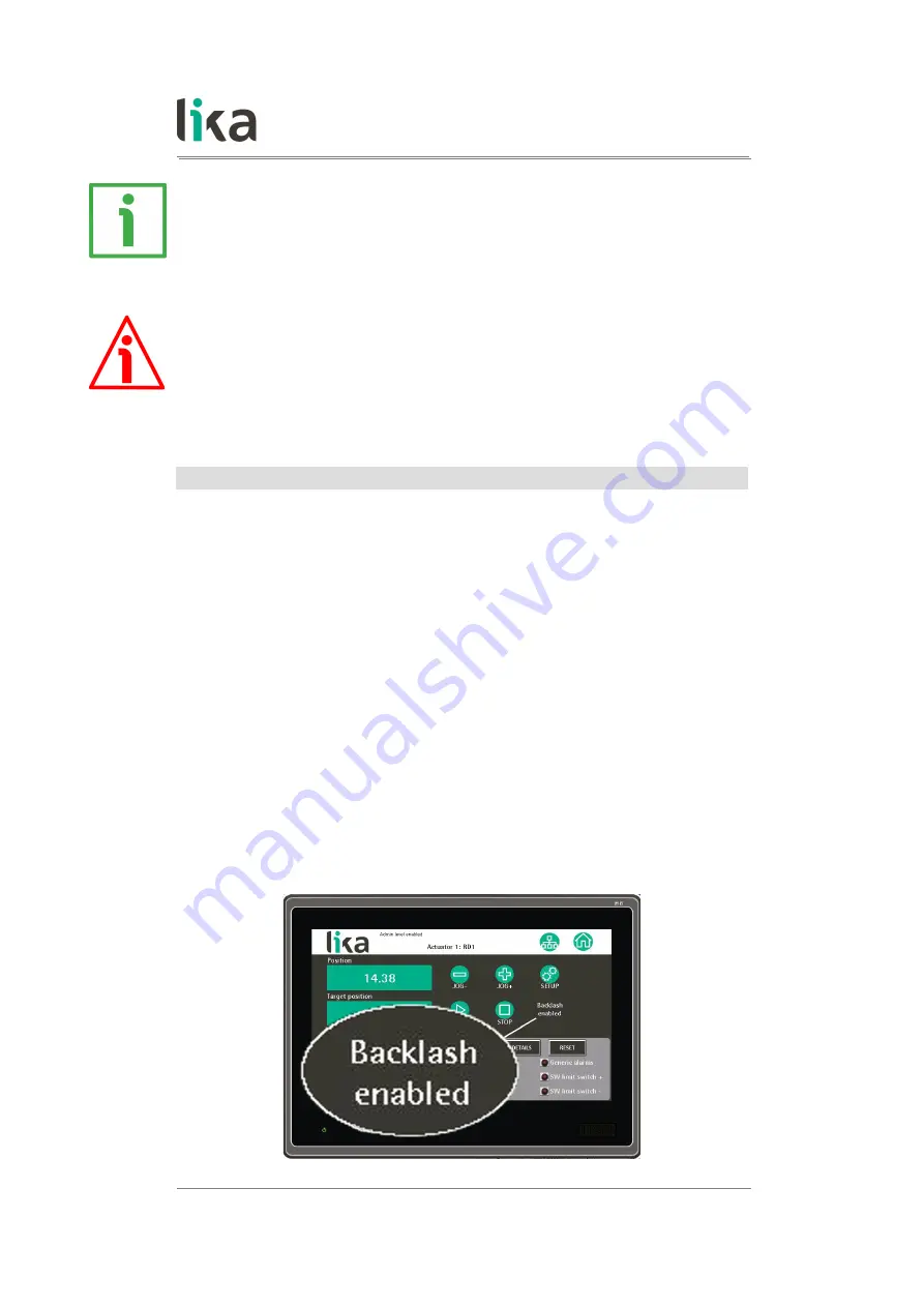
When the  

Backlash direction

  function is enabled and active, the  

BACKLASH

ENABLED

 message appears in the 

Node control

 page as the compensation is

performed.
Default = OFF

MAN LDT10 E 1.2

HMI interface

32 of 44

Summary of Contents for Modbus LDT10

Page 1: ...User s guide LDT10 RS 485 version Smart encoders actuators...

Page 2: ...on herein is subject to change without notice and should not be construed as a commitment by Lika Electronic s r l Lika Electronic s r l reserves the right to make all modifications at any moments and...

Page 3: ...ctions 12 4 1 Connectors Figure 3 13 4 2 Ground connection 15 4 3 Node address Node ID 16 4 4 Data transmission rate Baud rate and parity bit 17 5 HMI interface 18 5 1 Preliminary information 18 5 2 S...

Page 4: ...nt to highlight the parts of the text where information of great significance for the user can be found user must pay the greatest attention to them Instructions must be followed strictly in order to...

Page 5: ...ms and just in time productions need frequent and costly format adjustments The automated multi axis systems such as in the plastics industry mold changers mobile stops the packaging lines and the woo...

Page 6: ...o liability for the customer s failure to comply with these requirements 1 2 Electrical safety Turn off the power supply before connecting the device connect the device according to the explanation in...

Page 7: ...ions and usage tips This panel is intended for indoor use only it is designed for a recessed installation into an industrial electrical cabinet ensure that enough free space is left at the rear to all...

Page 8: ...erial number when reaching Lika Electronic for purchasing spare parts or needing assistance For any information on the technical characteristics of the product refer to the technical catalogue Warning...

Page 9: ...04 151 mm 5 94 26 5 mm 1 04 137 mm 5 40 191 5 mm 7 54 138 mm 5 43 Weight 650 g 22 9 oz 3 2 Mounting the panel Figure 2 LDT10 touch panel is designed for a recessed installation into an industrial elec...

Page 10: ...e in the installation support Use the dimensions as shown in Figure 1 and in the table above to provide the rectangular mounting cutout Remove the burrs made while cutting Mount the panel through the...

Page 11: ...th water distilled or demineralized water is suggested or isopropyl alcohol Do not use abrasive fabrics or materials such as paper towels even though they are soft as they can scratch the display Do n...

Page 12: ...rforming any electrical connection Figure 3 Electrical connections 1 3 pin connector Power supply 2 USB service port Firmware upgrade see on page 39 3 DSub 9 pin female RS 485 COM1 port MODBUS interfa...

Page 13: ...6 MODBUS B RS 485 2 5 Not connected 7 9 Not connected RD1A RD12A Power supply M12 4 pin male connector A coding Pin Function 1 24Vdc 10 motor 2 24Vdc 10 controller 3 0 Vdc motor and controller 4 Not c...

Page 14: ...e 1 2 Not connected 3 GND RS 485 4 MODBUS A RS 485 5 MODBUS B RS 485 RD5 RD52 Power supply M12 4 pin male connector A coding Pin Function 1 24Vdc 10 motor 2 24Vdc 10 controller 3 0 Vdc motor and contr...

Page 15: ...RS 485 Low WARNING For comprehensive information on the electrical connection of the DRIVECOD rotary actuators please refer to the specific documentation regarding the MODBUS interface models 4 2 Grou...

Page 16: ...uest to an individual Slave Before networking a device the univocal address must be set The node address is set via hardware in each device by using the dip switches located inside the enclosure LDT10...

Page 17: ...tion For detailed information please refer to the specific documentation of the actuator 4 4 Data transmission rate Baud rate and parity bit HMI LDT10 interface allows 9600 bits s data transmission ra...

Page 18: ...mode L1 full control mode L2 full control mode Home page Network page See on page 25 L0 display mode L1 display mode L2 full control mode See on page 23 L0 access denied L1 access denied L2 full cont...

Page 19: ...vices with the node positions Once you install one actuator in the page after pressing the key and exiting the page any further access will be allowed to the Level 2 Administrator users only Otherwise...

Page 20: ...n page 21 to gain access to the functions of the level 1 enter the Level 2 Administrator password 2233 see the 5 3 3 Level 2 Administrator section on page 22 to gain access to the functions allowed fo...

Page 21: ...th the node positions For comprehensive information please refer to the 5 2 Starting the interface for the first time section on page 19 NOTE When the Level 0 User is enabled no message appears in the...

Page 22: ...have competent knowledge skills and experience To activate the level 2 functions you must enter the password 2233 The Admin level enabled message appears in the white background menu at the top of the...

Page 23: ...rting the interface for the first time section on page 19 WARNING Before networking a device the univocal address must be set The node address is set via hardware in each device by using the dip switc...

Page 24: ...scription max 8 digit long in the field on the right of the Actuator 1 label the description will appear in all pages of the interface to identify the device having the node address 1 As soon as you p...

Page 25: ...d to access the protected pages or functions for more information please refer to the 5 3 Safety levels section on page 19 to enter the Network setup page to move back to the Home page to enter the No...

Page 26: ...dvanced node setup pages to set the parameters and check the status of each actuator For any information please refer to the 5 6 Node control page section on page 26 5 6 Node control page When you pre...

Page 27: ...s only see the 5 8 Node setup page section on page 30 For a comprehensive description of the parameters please refer to the User s guide of the specific actuator in the Status section on the bottom ri...

Page 28: ...d register in the User s guide of the specific actuator WARNING As soon as you press the JOG and START keys the axle starts moving Before pressing the keys please make sure that the movement can be ac...

Page 29: ...an alarm condition of the Slave device provided that the fault condition has ceased press the RESET key in the Node control page The RESET key is available to the level 1 and level 2 users only Refer...

Page 30: ...re the actuator and the travel for the specific application is available For the list of the advanced parameters that are used to configure the mechanical and electronic characteristics of the specifi...

Page 31: ...are described hereafter Decimals It sets the number of digits for the decimal places that are used to show the Position value the Target position value and the Speed value in the Home and Node contro...

Page 32: ...learance or lost motion in the mechanism caused by gaps between the parts As it is unidirectional this parameter further allows to set whether the compensation is performed when the axle moves forward...

Page 33: ...irection so reaching the target position properly As shown in the figure below if you set Backlash direction POSITIVE the backlash compensation is performed only when the axle moves toward positive ta...

Page 34: ...to an idle device i e running disengaged from the load Furthermore they are intended to ensure a standard and safe operation which not necessarily results in smooth running and optimum performance Th...

Page 35: ...display this page yet the functions are available to the Level 2 Administrator users only By pressing the ADVANCED PARAMETERS key in the Node setup page you enter the Advanced node setup page In this...

Page 36: ...le and even necessary to enter new parameters instead of the factory default settings in particular it may be necessary to change velocity acceleration deceleration and gain values WARNING As soon as...

Page 37: ...d for a work or production process In this application all the parameters are specific to each actuator except for the target position only the target position is specific to the recipe In the Node se...

Page 38: ...n the Target column on the right next to each actuator We suggest entering the Node control page see the 5 6 Node control page section on page 26 setting the required target value and then checking th...

Page 39: ...es thus their stop will not be immediate WARNING A safety push button for emergency power off must be installed to shut off the motor power supply and immediately stop the axles in case of emergency s...

Page 40: ...ully please contact Lika Electronic Technical Assistance After Sale Service To upgrade the firmware program please proceed as follows 1 switch the power supply off 2 copy the PRP file provided by Lika...

Page 41: ...M FILE key the Open dialogue box appears on the screen you must open the folder where the firmware upgrading PRP file released by Lika Electronic is located 8 select the PRP file and confirm the choic...

Page 42: ...allation 10 as soon as the operation is carried out if it has been completed successfully the Panel Setup page will be displayed 11 turn the power supply off and then on again to start the panel in th...

Page 43: ...This page intentionally left blank...

Page 44: ...e 1 0 09 09 2015 First issue 2 1 1 1 22 04 2016 New software version 2 2 1 2 07 11 2016 New software version RD6 actuator implemented 2 3 Lika Electronic Via S Lorenzo 25 36010 Carr VI Italy Tel 39 04...

Reviews: