background image

EM58 PA

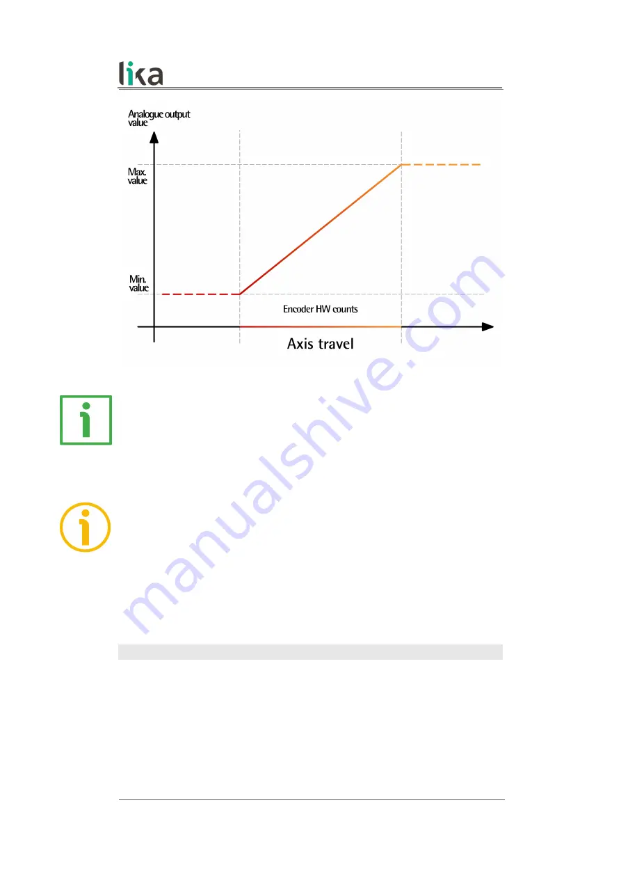
For instance, if 

Output type

 = VOLTAGE; 

Output range

 = 0 – 5V; 

Encoder HW

counts

 = 4,096, then the encoder will provide a fixed voltage level of 0 V for the

33 552 384 positions before the origin of the travel; a voltage level between 0 V
(origin of the travel, position 0) and 5 V (end of the travel, position 4,095) for
the  positions of the  axis;  a  fixed  voltage  level  of  5  V  for  the  33  552  384
positions after the last point of the travel.

NOTE

Please note that in this encoder the maximum number of physical counts per
turn is 4,096 (2

12

), while the maximum number of physical revolutions is 16,384

(2

14

); thus the overall number of information is 67 108 864 (2

26

). However the

DAC has a 16-bit (65,536 information) resolution. So you are allowed to arrange
the number of counts per turn and the number of revolutions as you prefer; yet
the overall analogue resolution will be limited to 16 bits.

Encoder HW counts

This parameter is available only when the  

Programming mode: Prog (single

ramp)

 is enabled.

It   sets   the   length   of   the   displacement   you   need   to   measure   and   control
expressed in encoder information (counts). When needed, calculate the portions
of a turn by considering the physical 

Counts per revolution

. For instance: if the

axis travel is 1.5 turn long, enter: 4,096 

*

 1.5 = 6,144 counts.

Default = 67 108 864 (min. = 1, max. = 67 108 864)

MAN EM58 PA E 1.1

Software and configuration parameters

48 of 60

Summary of Contents for EM58 PA Series

Page 1: ...versions Free of charge programming software Suitable for the following models EM5812 16384PA EM58S12 16384PA EMC5812 16384PA EMC5912 16384PA EMC6012 16384PA Table of Contents Preliminary information...

Page 2: ...on herein is subject to change without notice and should not be construed as a commitment by Lika Electronic s r l Lika Electronic s r l reserves the right to make all modifications at any moments and...

Page 3: ...fixing plate 16 4 Electrical connection 17 4 1 Cable and connectors connections 17 4 2 T12 cable specifications 17 4 3 M23H 12 pin counter clockwise connector specifications 18 4 4 M12 12 pin connecto...

Page 4: ...SOLUTION SETTING box 39 Programming mode Start Stop single ramp 41 1 Start teaching 43 2 Stop teaching 43 Programming mode Start Stop cyclic ramp 44 1 Start teaching 46 2 Stop teaching 46 Programming...

Page 5: ...Value not valid preset greater than the maximum position 56 6 Default parameters list 58...

Page 6: ...on between start and stop 36 Encoder travel not valid unable to reach the minimum stroke 36 Error creating the file 56 Error reading the file 56 L Load default parameters 32 M Max number of revolution...

Page 7: ...t to highlight the parts of the text where information of great significance for the user can be found user must pay the greatest attention to them Instructions must be followed strictly in order to g...

Page 8: ...ogrammable encoder is available in both hollow and solid shaft versions The parametrization and set up of the EM58 PA programmable encoder is achieved through a software expressly developed and releas...

Page 9: ...the customer s failure to comply with these requirements 1 2 Electrical safety Turn OFF the power supply before connecting the device connect according to explanation in the Electrical connection sect...

Page 10: ...nit or its shaft delicate electronic equipment handle with care do not subject the device and the shaft to knocks or shocks respect the environmental characteristics of the product unit with solid sha...

Page 11: ...mber when reaching Lika Electronic for purchasing spare parts or needing assistance For any information on the technical characteristics of the product refer to the technical catalogue Warning encoder...

Page 12: ...flexible coupling 1 on the encoder shaft fix the encoder to the flange 2 or to the mounting bell by means of the screws 3 secure the flange 2 to the support or the mounting bell to the motor mount the...

Page 13: ...n using a mounting bell optional kit code PF4256 NOTE In order to guarantee reliability over time of the encoder mechanical parts we recommend a flexible coupling to be installed between the encoder a...

Page 14: ...sing a locknut mount the encoder on the motor shaft using the reducing sleeve 8 if supplied Avoid forcing the encoder shaft insert the anti rotation pin 1 into the slot on the flange of the encoder th...

Page 15: ...us page mount the encoder on the motor shaft using the reducing sleeve 8 if supplied Avoid forcing the encoder shaft fasten the fixing plate 4 to the rear of the motor using two M3 x 8 cylindrical hea...

Page 16: ...der shaft make sure the anti rotation pin 6 is inserted properly into the fixing plate 7 fix the collar 3 to the encoder shaft A min 8 max 18 mm NOTE You are strongly advised not to carry out any mech...

Page 17: ...lt Yellow 3 4 0Vdc RS 232 Brown 4 10 Iout Grey 5 5 0Vdc analogue Violet 6 3 Vout Pink 7 6 Counting direction Blue 8 8 Preset White 9 7 Not connected Black 10 12 13Vdc 30Vdc Brown_Green 11 2 0Vdc Power...

Page 18: ...n always use shielded cables The cable shielding must be connected properly to the metal ring nut 3 of the connector in order to ensure a good earthing through the frame of the device To do this disen...

Page 19: ...program connect the device to the personal computer through a serial port Should the personal computer not be equipped with a serial port you must install a USB RS 232 converter easily available in t...

Page 20: ...tput is enabled Output type CURRENT It is intended to signal an error such as a circuit break As soon as the Fault signal is activated a message is also invoked to appear in the DIAGNOSTICS box of the...

Page 21: ...logue output Figure 1 4 9 1 Fault output connected to a PLC input Figure 2 No encoder error PLC input Low 0Vdc Encoder error PLC input High Vdc EXAMPLE Vdc 24V R1 47 R1 I Vdc R2 I 4 7 mA R2 5 k MAN EM...

Page 22: ...ignal After having enabled the analogue output by setting the Enable analog output parameter in the ENCODER CONFIGURATION box of the CONFIGURATION page the user is allowed to choose the type of output...

Page 23: ...ter having enabled the analogue output by setting the Enable analog output parameter in the ENCODER CONFIGURATION box of the CONFIGURATION page the user is allowed to choose the type of output either...

Page 24: ...CCW INVERTED When the counting direction is set to CW STANDARD Positive counting direction CW STANDARD if the Counting direction input has LOW logic level 0Vdc the encoder will provide the increasing...

Page 25: ...loaded to the encoder next to the Preset parameter in the PRESET box see on page 34 By default the preset value is 0 Connect the Preset input to 0Vdc if not used To set the preset connect the Preset...

Page 26: ...EM58 PA 4 15 Recommended voltage analogue output circuit MAN EM58 PA E 1 1 Electrical connection 26 of 60...

Page 27: ...port The executable file LIKA_PROGRAMMABLE_ENCODER_Vx_x EXE is available at our website The program is designed to be installed simply by copying the executable file to the desired location and there...

Page 28: ...the serial port see on page 28 Configuration button it allows to enter the page where the configuration parameters are located see on page 33 Load save configuration button it enters the page where t...

Page 29: ...e the fields in the ENCODER box show a question mark as the connected device has not been identified yet Before starting the identification process please make sure the unit is connected properly to t...

Page 30: ...vigation bar become active On the contrary if the program is not able to establish a connection to the encoder a red X X appears next to the DEVICE SEARCH button Should this happen please check that t...

Page 31: ...Make sure that the power supply voltage is correct Also check that the serial cable characteristics meet the requirements described in the 4 7 RS 232 serial connection section on page 19 WARNING Make...

Page 32: ...type of output of the device is shown next to this item PARALLEL SSI or ANALOGUE Version When the connection is established properly and the device is detected the software and hardware versions of t...

Page 33: ...he CONFIGURATION page This page allows the operator to start programming and monitoring the unit The following window will appear 5 3 1 POSITION box In the POSITION box at the top left of the page the...

Page 34: ...ox is set to ENABLED on the contrary if DISABLED is set they are not available The functions in this box are used to set and activate the preset Preset This function is available only if the parameter...

Page 35: ...ommand after having stopped the encoder at position 0 195 V Position 0 195 after having sent the command by pressing the Activate preset button Position 4V Turns 13107 Counts rev 819 So we need the en...

Page 36: ...on page 25 5 3 3 DIAGNOSTICS box This box is designed to show the error messages which could be triggered while programming the encoder Hereafter are the available error messages Encoder travel not v...

Page 37: ...STANDARD if the Counting direction input see on page 24 has LOW logic level 0Vdc the encoder will provide the increasing count when the shaft is turning clockwise and the decreasing count when the sha...

Page 38: ...t can be enabled disabled by setting the Enable analog output parameter in the same ENCODER CONFIGURATION box Default voltage Output range After having enabled the analogue output by setting the Enabl...

Page 39: ...the selected range Output range see on page 41 Programming mode Start Stop cyclic ramp TEACH IN it allows to programme the encoder by considering directly the physical travel of the application you ne...

Page 40: ...the physical travel of the application you need to measure and control the travel is defined in a ramp which is then repeated cyclically as soon as the final position of the travel is reached then the...

Page 41: ...ut range the overall information to be output which is set next to the Output range item is defined over the travel of the specific application and is comprised between the ends of the axis the origin...

Page 42: ...e encoder using the START STOP single ramp programming mode proceed as follows move the axis to the origin of the physical travel of the application you want to measure and control in other words move...

Page 43: ...ected output range to the physical position you have moved the axis to end of the axis WARNING If the start position 1 Start teaching and the final position 2 Stop teaching match i e you do not change...

Page 44: ...l is reached then the minimum signal level of the selected range is output to start a new ramp and so on The set output range the overall information to be output which is set next to the Output range...

Page 45: ...ng mode proceed as follows move the axis to the origin of the physical travel of the application you want to measure and control in other words move it to the point where the travel starts press the 1...

Page 46: ...ected output range to the physical position you have moved the axis to end of the axis WARNING If the start position 1 Start teaching and the final position 2 Stop teaching match i e you do not change...

Page 47: ...ected range Output range The length of the travel you need to measure and control must be set next to the Encoder HW counts item and is expressed in counts The set output range the overall information...

Page 48: ...84 214 thus the overall number of information is 67 108 864 226 However the DAC has a 16 bit 65 536 information resolution So you are allowed to arrange the number of counts per turn and the number of...

Page 49: ...while the maximum number of physical revolutions is 16 384 214 thus the overall number of information is 67 108 864 226 However the DAC has a 16 bit 65 536 information resolution so the overall analog...

Page 50: ...selected range is output to start a new ramp and so on The initial position of the travel is the minimum value of the selected output range Output range the final position is the maximum value of the...

Page 51: ...hus the overall number of information is 67 108 864 226 However the DAC has a 16 bit 65 536 information resolution so the overall analogue resolution will be limited to 16 bits Encoder HW counts This...

Page 52: ...of revolutions It displays the number of physical revolutions the device is able to output namely the multiturn resolution 16 384 turns i e 214 NOTE Please note that in this encoder the maximum number...

Page 53: ...while the maximum number of physical revolutions is 16 384 214 thus the overall number of information is 67 108 864 226 However the DAC has a 16 bit 65 536 information resolution so the overall analog...

Page 54: ...s the SAVE NEW CONFIGURATION TO FILE button As soon as you press the button the Save as dialogue box appears on the screen and the Starting process message appears on the display box below in the page...

Page 55: ...play box below in the page The operator must select the folder and then the file where the configuration has been saved When you press the OPEN button to confirm the dialogue box closes If the process...

Page 56: ...Prog single ramp or Programming mode Prog cyclic ramp a number of information for the travel greater than the maximum number of HW information available for the encoder The maximum number of informat...

Page 57: ...hree digits thousandths further digits in the fractional part are subject to round off Separate the integer part from the fractional part using the decimal point decimal comma is converted into decima...

Page 58: ...set enabled Positive counting direction CW standard Output type voltage Output range 0 5V Programming mode Start Stop single ramp Encoder HW counts in Programming mode Prog single ramp 67 108 864 Enco...

Page 59: ...This page intentionally left blank...

Page 60: ...r Low Voltage Limited Energy or Energy Source not exceeding 30 Vdc Refer to the order code for supply voltage rate Ce dispositif doit tre aliment par un circuit de Classe 2 ou tr s basse tension ou bi...

Reviews: