background image

Lightwave Communications 

PC ServerSwitch 2x16 

www.lightwavecom.com 


Page 19 of 24

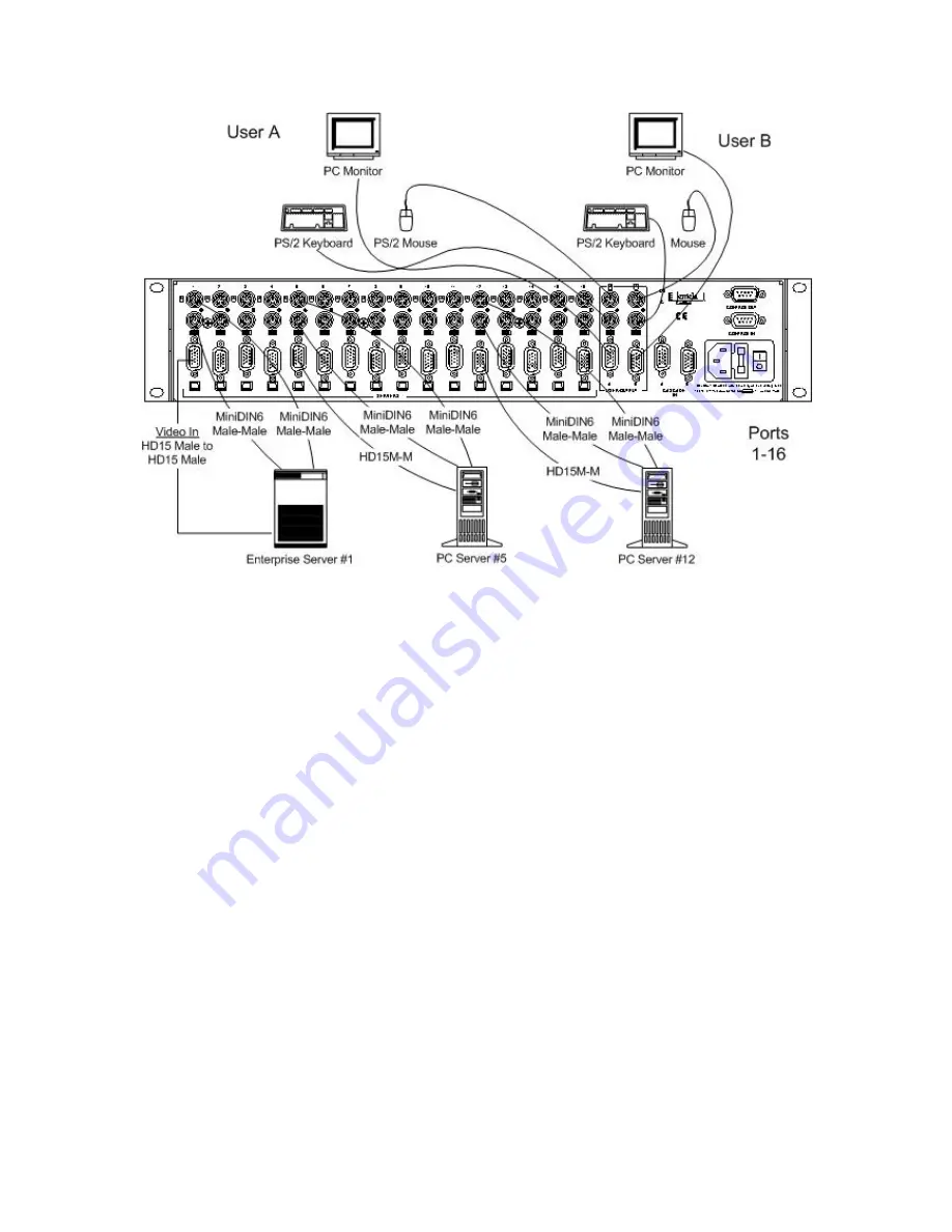
Figure 7 -- PC Server Switch 2x16 -- Rear Panel Connections, 3 Servers 

STEP 3 -- Connecting CPUs 

Referring to Figure 4, connect a single PC to the PC ServerSwitch 2x16 and verify 
its operation. Use the cables that were purchased with the PC ServerSwitch 2x16 
to attach the PC. Connect the cables in the following order: 

Make certain that all PCs are powered off when connecting them to the PC 
ServerSwitch 2x16. It is important to note that some servers do not allow for 
keyboards to be connected and disconnected during operation. This may cause 
them to halt.  

1) A Mini-DIN6 male-to-male cable from the Server keyboard connector to 
the PC ServerSwitch 2x16. Maximum length is 25 feet. 

2) A Mini-DIN6 male-to-male cable from the Server mouse connector to the 
PC ServerSwitch 2x16. Maximum length is 25 feet. 

3) An HD15 male-to-male video cable from the Server graphics adapter to 
the PC ServerSwitch 2x16.  

Once step three is complete, continue to connect the remaining PCs. Repeat step 
three until all of the devices are connected.  

NOTE!    CPUs can be connected to any port. It is not necessary to use Port 1 

as the first connection, Port 2 as the second, etc.  

Summary of Contents for serverswitch 2X16

Page 1: ...User Manual September 2001 Part Number 15 00 030 Revision A...

Page 2: ...om au Internet www lightwavecom com au LCI Europe Zaubzerstra e 11 Munich D 81677 Germany 49 89 306 3810 Fax 49 89 306 3812 Email office lightwave de Internet www lightwave de PC ServerSwitch 2x16 Pro...

Page 3: ...nu Jump to Port 10 3 2 System Setup 11 3 2 1 System Setup Port Setup 12 3 2 2 System Setup Menu Window Setup 13 3 2 3 System Setup Server Window Setup 14 3 3 Front panel LCD Display 14 Front Panel Con...

Page 4: ...ter 4 line backlit LCD display The top two lines display Port data for the currently selected server port and the bottom lines are dedicated to real time status monitoring The PC ServerSwitch 2x16 can...

Page 5: ...1600 x 1200 pixels Impedance balanced RGB lines 75 ohms Keyboard power sensing On screen menus Backlit front panel LCD display Non volatile memory for server names options Video cascade port for casc...

Page 6: ...y of the keyboard and mouse configuration When the user switches from one port to another the keyboard is set up just as it was prior to switching to another port The mouse behaves in a similar manner...

Page 7: ...ress the Scroll Lock key twice Up Arrow Down Arrow and keys on number pad Enter select or scroll through options Esc to exit or to back up one level Most options have a single character hot select key...

Page 8: ...rver ports using N Prev unit go to the Previous page of eight server ports using P Esc exits press Esc to exit the server window If Scanning is enabled port scanning will start upon exiting NOTE You c...

Page 9: ...ey on your keyboard Return to the main menu by pressing Ctrl Ctrl or Scroll Lock twice To exit the on screen menus press Esc until no more screens are shown Use the and keys on the number pad of your...

Page 10: ...ver 2 2 Print Server 3 Email Server 4 Engineering 5 Enterprise 6 Firewall 7 Fax Server 8 Next unit Esc exits The screen will change to the following Enter port prompt no Auto scan Enter port Disabled...

Page 11: ...key to select your desired value Auto Scan Duration Select the length of time between 2 to 30 seconds that each port will be scanned during auto scan Error Message Duration Select the amount of time 2...

Page 12: ...y be enabled or disabled system wide if required Valid characters include A through Z a through z digits 1 through 9 and 0 and plus minus slash period and colon The symbol on screen represents Auto Sc...

Page 13: ...moved U p D own L eft or R ight You may also select the Line e g move Up and press Enter to move the display or change the color option as desired The color choices include 8 color options for each o...

Page 14: ...eys and pressing Enter to move the window and or change colors Use the color and position options listed in Section 3 2 2 To select a specific function press the hot key letter that is capitalized hig...

Page 15: ...o select the next Server number If you reach the highest port number the next value is disabled and then it restarts at Port 1 Press and release the Down arrow button to select the previous server num...

Page 16: ...o a standard 19 inch rack D The PC ServerSwitch 2x16 has a universal power supply which requires 85 264 VAC 47 63 Hz at 1 ampere Power consumption is 24 watts It is important for each unit to be suppl...

Page 17: ...erSwitch 2x16 installation can be expanded at any time without interfering with servers connected to existing switches Figure 5 PC ServerSwitch 2x16 Front and Rear panels STEP 1 Unpacking the Items Ve...

Page 18: ...cascaded unit 11 Monitor connector for User Console B or Output B if a cascaded unit 12 Video Cascade A In Accepts video from Output A on the next 2x16 unit 13 Video Cascade B In Accepts video from O...

Page 19: ...hat some servers do not allow for keyboards to be connected and disconnected during operation This may cause them to halt 1 A Mini DIN6 male to male cable from the Server keyboard connector to the PC...

Page 20: ...g the PC ServerSwitch 2x16 This section only applies to configurations with more than one PC ServerSwitch 2x16 Up to six 6 PC ServerSwitch 2x16 units may be cascaded for a maximum of 96 server ports a...

Page 21: ...essary for cascading units Follow this procedure for as many Aux units If more units are cascaded connect the Control Out port to the Control In port of the next unit to be cascaded using a DB9 Female...

Page 22: ...pressing the Scroll Lock key twice 2 Once at the System Setup System Setup System Setup System Setup menu access the System Setup submenu by pressing the F1 F1 F1 F1 key 3 Press the F12 F12 F12 F12 ke...

Page 23: ...pressing Cntl Cntl on any attached keyboard or pressing the Scroll Lock key twice 5 From the System Setup System Setup System Setup System Setup menu press the F1 F1 F1 F1 key to access the defaults...

Page 24: ...then be saved 11 You will get a prompt stating Flash Programming Complete after less than a minute Finally it will state Starting System 12 After you get the Starting System prompt the Flash update is...

Reviews: