8. Lightware Device Controller
UBEX series – Matrix Application Mode – User's Manual
98
8. Lightware Device Controller
UBEX series – Matrix Application Mode – User's Manual
98
MA
TRIX APPLIC
A
TION MODE
Applied F-series endpoint firmware package: v1.4.1 | Applied R-series endpoint firmware package: v1.4.1 | Applied MMU firmware package: v1.2.1 | LDC software: v1.34.0b2
8.19. Video Wall Setup
The UBEX devices can be arranged to a video wall in Matrix mode. This section is about the UBEX video wall,
including a step-by-step tutorial to create a new wall, and the handling of the system in the Lightware Device
Controller (LDC) software.
#videowall #vw #layout #zone
8.19.1. Tutorial - Creating a New Video Wall
Navigate to the
Video Wall Setup
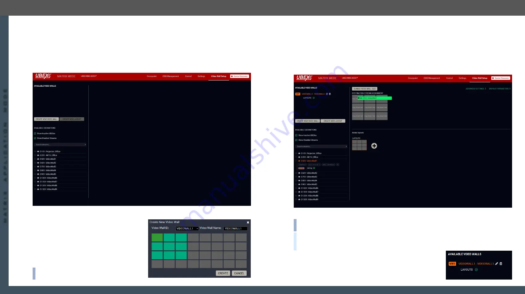
menu. The default state is the empty window (no video wall is defined).
Default state of the Video wall setup menu
Step 1.
Click on the
Create New Video Wall
button. A wizard
pops up where you can add the size of the wall.
Click on the upper left corner of the wall at first,
then click on the lower right. A unique name can
be added in the
Video wall name
field, the default
for the first one is VIDEOWALL1. Click on the
Create
button when ready.
A 3x3 wall is created in our example.
INFO:
The UBEX video wall system supports the
display devices
up to 8x4
(column x row).
Step 2.
The next step is adding the destination devices to the wall where the content will be displayed. The
available
destination streams
appear on the lower left side of the window. Click on a destination stream
to see its
tags
. You can search between the destination streams using the
Search streams
field. The
tags are also searchable. Clicking on the
icon launch the
Identify Stream / Identify Display
feature.
Drag and drop
the destination streams to assign them to the wall. If a stream has been assigned to the
wall, it will disappear from the list.
The video wall size can be changed by clicking on the
Change video wall size
button.
Destination stream assignment
INFO:
Only the
HDMI out 1
port can take part in the video wall, the HDMI out 2 does not participate but can
transmit any other stream during the operation of the video wall.
TIPS AND TRICKS:
Adding unique names and tags to the destination streams
before
defining the video
wall makes easier the configuration steps. See the details in the
Video Destination Port Properties Window
section.
Step 3.
Complete the video wall. Click in the
(Activate)
icon next to of
the name of the video wall. When the icon changes to
and the
name changes to white, the video wall becomes
active
.


