3. Product Overview
DA2DVI-HDCP-Pro – User's Manual
8
Product Overview
The following sections are about the physical structure of the device, input/
Ý
Ý
Ý
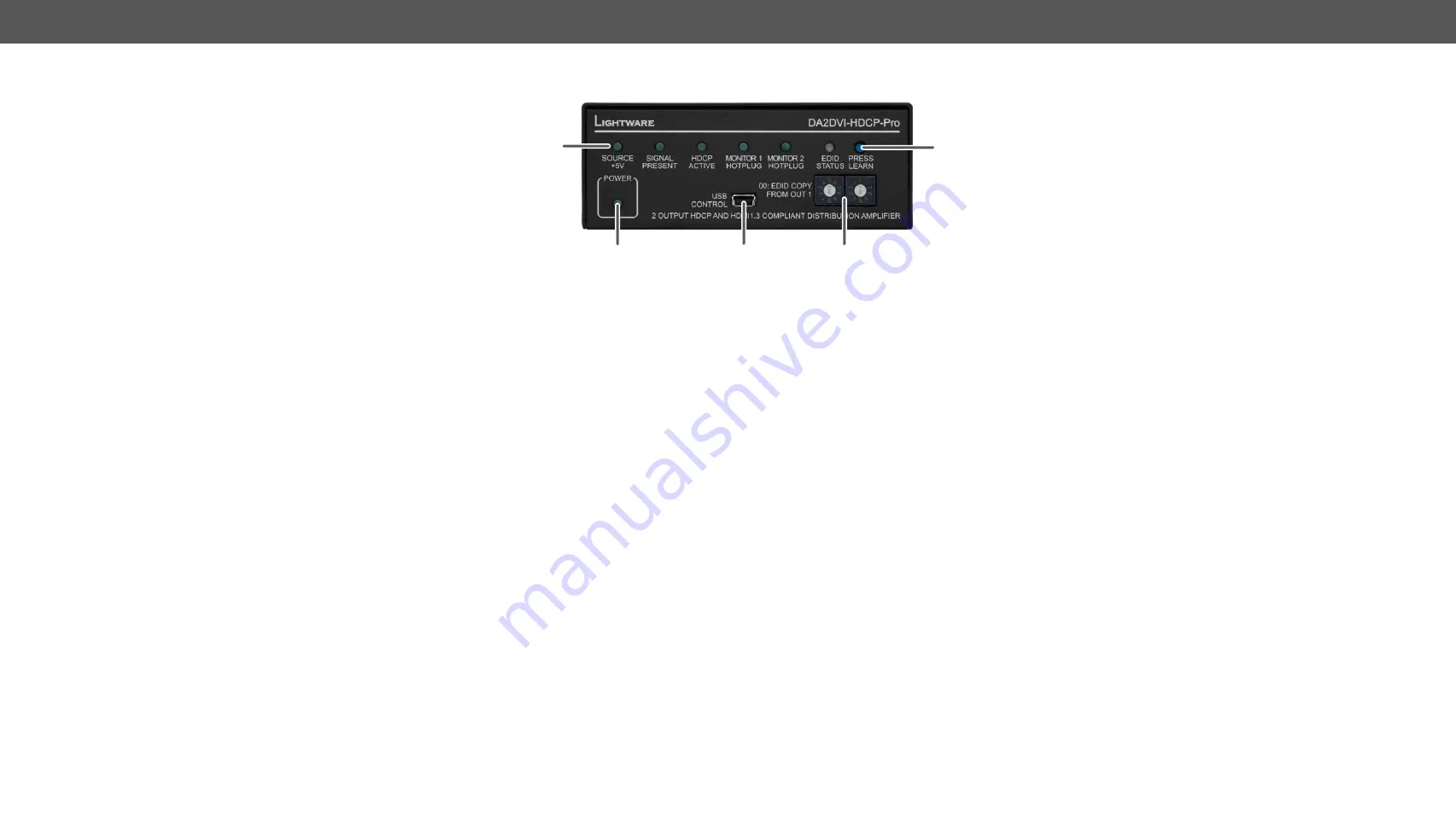
3.1. Front View
2
1
3
4
5
1
Status LEDs
Displaying the current state of the input and
output connections. See the details below.
2
Power LED
Indicates if the device is powered on.
3
USB Control
Advanced EDID management and firmware
upgrades are available via the USB interface.
4
Rotary
Switches
The rotary switches select one of the EDID
memory addresses. For more information see
the
section.
5
Learn Button
Stores the EDID of the display device attached
to OUTPUT 1 in the selected memory address.
To learn the EDID, select an appropriate
address with the rotary switches and press
and hold the LEARN button for three seconds.
For more information see the
section.
Status LEDs
5V
Indicates if +5V power signal is sent to pin 14 of
the INPUT connector by the DVI source (PC, Laptop,
etc).
Signal
Present
BLINKING (slow): HDMI signal is present on INPUT
and OUTPUT ports.
BLINKING (fast): HDMI to DVI conversion is enabled.
See more information in
section.
HDCP Active
BLINKING (green): HDCP is disabled. For more
Monitor
Hotplug
A powered sink (or matrix switcher, repeater, etc.) is
connected to the OUTPUT connector and sends a
valid hotplug signal on pin 16 through the DVI cable.
EDID Status
LED
EDID status (green)
: the selected EDID is valid;
EDID status (red):
the selected EDID is invalid.
FW version display
: During startup it displays the
firmware version.
EDID read status
(BLINKING green):
the EDID is valid;
EDID read status
(red):
the EDID is invalid or missing.
The function is available for both outputs and
saves the EDID to the Last attached Monitor’s EDID
memory.
EDID learn process (BLINKING green)
: succeed
EDID learn process (BLINKING red)
: failed
Firmware upgrade (BLINKING red and green):
The LED
blinks red and green during the upgrade.


