
Page 2 of 4
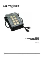
AS42L COMPACT DIMMER
Revision 2.2
OWNER’S MANUAL
06/01/2022
www.lightronics.com
Lightronics Inc.
509 Central Drive, Virginia Beach, VA 23454
Tel: 757 486 3588
DESCRIPTION
The AS42L is a compact four channel light dimmer.
It has a maximum capacity of 1200 Watts per
channel and a maximum total load capacity of 4800
Watts. It is supplied with two input power cord stubs
which may be connected to two different 120 VAC
power services. The AS42L is intended for INDOOR
USE ONLY. The unit operates using the Lightronics
LMX-128 multiplex protocol. The AS42L may be
operated in a relay (non-dim) mode. The unit will
also function as a chaser and has several preset
chase patterns which may be used.
AS42L END VIEW
INSTALLATION
LOCATION: Locate the unit vertically with control
signal connectors on the bottom in a well ventilated
area away from moisture and heat. Two ½” holes
are provided on the dimmer top cover to install a
lighting bar pipe clamp and suitable safety cables.
POWER CONNECTIONS: Extending from the
chassis are two 20 amp line cords for connection to
two separate 120 VAC, 20 Amp grounded services.
Total capacity of the AS42L is 4800 Watts.
LOAD CONNECTIONS: There are four numbered
duplex outlets on the top of the unit. Each provides
two connections for each of the output channels.
You can connect up to 1200 Watts of lighting to
each channel.
CONTROL SIGNAL CONNECTIONS:
The male three pin XLR connector on the unit end
panel connects to the control console. The female
connector is for connection to additional dimmers.
The AS42L dimmer is compatible with the
Lightronics LMX-128 and NSI/Sunn three wire
multiplexed protocol. If you have older Lightronics
dimmers which run in the obsolete Lightronics mode
only, contact Lightronics for information on changing
the mode. When using multiple dimmers, ALL
dimmers MUST be in the SAME mode.
CONTROL SIGNAL WIRING:
XLR Connector Pin #
Signal Name
1
LMX Common
2
Console Power
(+15Volts DC)
3
Multiplex Signal
Applies to input and output connector
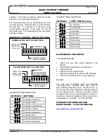
OPERATION
NORMAL MODE (Non-Chaser):
A green LED in the end panel will indicate that a
valid LMX-128 control signal is applied to the unit. A
DIP switch block on the end panel selects the
starting channel number of the dimmer. The seven
right hand switches control this function. For
example, if all switch positions are down - the
dimmer will respond to channels 1-4. Raising the
switch on the far right will set the dimmer to respond
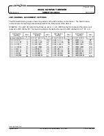
to channels 5-8. A complete table of channel
assignments is provided in this manual. You can
address up to 512 channels with multiplex control.
RELAY MODE
Pairs of channels (1/2 and/or 3/4) may be switched
into the relay mode. In this mode the output of these
channels will be either off or full on depending on the
control console channel setting. The trip point for
turn on is aprox. 50%. The two left hand switches on
the DIP switch block control relay mode channel
selection. The UP position of the switches invokes
RELAY MODE.
CHASER MODE:
When operating in the chaser mode the AS42L
becomes independent of the control console and
other dimmers. The green LED indicator is OUT
when in the chaser mode. Chaser mode is turned
on and off by one of the DIP switches on the end of
the unit. A diagram on the unit cover shows the
switch settings for controlling chaser operation.
Eight different chase patterns are available. A
"bounce" condition may be imposed on several of
the chase patterns by setting one of the DIP


