Liftsafe Fall Protection RoofGuard Classic HGC-KIT-09 User Instruction Manual Download Page 9

Page 9 


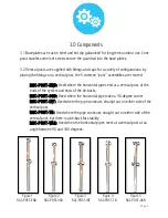
5.5 Use a 3/16” hex drive bit (provided) or wrench, and torque baseplate screws to 25ft-
lbs. All set screws for stacked plates must be secured against the wall of the vertical posts. 

5.6 Once torqued the set screw can be ‘marked’ with the blue crayon (provided) to provide 
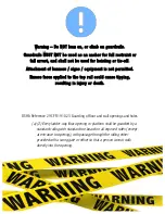
a visual indicator that the screw has been secured and warn of tampering. (If the blue wax 
is removed, it may indicate a tool was re-inserted in the set-screw.) 

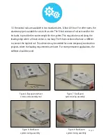
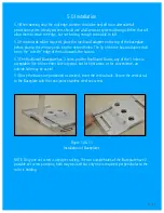
5.7 If toe-boards are to be used, the lumber can be cut and placed under the toe-board 
adapter (from 5.2). The toe-board adapter can be lifted (sliding up the rails) to place the 
lumber, and then lowered back onto the top of the lumber. Using the three holes provided, 
secure the toe-board to the toe-board adapter with three #10 or #12 screws 1.5” or 
longer. Longer screws should not protrude from the lumber where they may introduce a 
hazard to workers.  

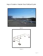
5.8 Once all vertical posts are set, the horizontal rails can be placed into the fittings and 
secured with the hex drive bit (provided). To provide a visual indicator that the screw has 
been secured and warn of tampering mark set screw with crayon. (If the blue wax is 
removed, it may indicate a tool was re-inserted in the set-screw.)  

5.9 Working form one end to the other, complete the assembly of the rails as per the layout 
drawing. Once complete, the system should be reviewed to ensure the design is as per the 
layout drawing and each set screw has been torqued and marked. At this point the system 
is safe and ready for use.  

Page 9 

Summary of Contents for RoofGuard Classic HGC-KIT-09

Page 1: ...Page 1 User Instruction Guide for RoofGuard Classic Freestanding Guardrail System Liftsafe Fall Protection Inc RoofGuard Classic User Manual RGC UM 3 0...

Page 2: ...le of Contents Section Page Number 1 0 Application 4 2 0 System Requirements 4 3 0 Components 5 4 0 System Layout 7 5 0 Installation 8 6 0 Detailed Inspection and Maintenance Log 12 7 0 Warranty 13 8...

Page 3: ...ovided to the user of this system The user must read and understand these instructions or have them explained to them prior to using the system Alterations or misuses of this system or failure to foll...

Page 4: ...ultra light paving stone may be used under the base plates to facilitate safe stable contact with the roof surface As freestanding systems rely on friction between the baseplates and the roofing mate...

Page 5: ...tal pipes end at a vertical post at the ends of the system and ends of the tie backs RGC POST 90D Used where the horizontal pipe make a 90 degree corner RGC POST INT Used where the pipe continues stra...

Page 6: ...the leading edge where a 9 foot section is too long The 9 foot sections of rail use a stiffener to connect the top mid rail This element may be omitted for some temporary construction projects where...

Page 7: ...the system shall have a TIE Back perpendicular to the hazard roof edge extending 6 feet with 3 baseplates at the RGC End Post The tie back shall NOT be along a leading edge itself IE the RGC End Post...

Page 8: ...be on the outside edge of the rail towards the hazard 5 3 The RoofGuard Baseplate has 3 holes and for RoofGuard Classic any of the 3 holes is acceptable Use of the center hole is typical but for tigh...

Page 9: ...e lumber Using the three holes provided secure the toe board to the toe board adapter with three 10 or 12 screws 1 5 or longer Longer screws should not protrude from the lumber where they may introduc...

Page 10: ...Page 10 Figure 13 Figure 14 Image of Complete a Complete Classic RoofGuard System...

Page 11: ...applied to the top rail could cause tipping resulting in injury or death OSHA Reference 29 CFR 1910 23 Guarding of floor and wall openings and holes a 2 Every ladder way floor opening or platform sha...

Page 12: ...Page 12 6 0 Detailed Inspection and Maintenance Log Inspection Date Inspection Items Noted Corrective Action Taken Maintenance Performed Approved By...

Page 13: ...ent Upon notice in writing LFP will promptly repair or replace all defective items LFP reserves the right to elect to have any defective item returned to its plant for inspection before making a repai...

Page 14: ...Page 14 8 0 Notes...

Page 15: ...Page 15 Liftsafe Fall Protection 409 Harmony Road Ayr Ontario N0B 1E0 TF 1 800 977 2005 T 519 896 2430 F 519 896 2085 E info liftsafeinspections com W www fallsafetysolutions com...

Reviews: