


8
3
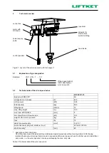
Assembly of the wire rope winch
3.1
Wire rope winch with wall bracket
dimension of the fastening points
Figure 2: Assembly of the wire rope winch with wall bracket
Prepare the assembly of the wire rope winch onto the wall according to the dimensions as shown in
Figure 2. Assemble the wire rope winch by the wall bracket. (Caution: The wall surface must be
vertical!)
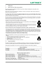
Caution!
The suspension points have to be calculated to withstand the forces created by the
winch with wall bracket.
Screws M10 according to DIN 933 and strength class 8.8 have to be used. A tightening
torque of 45 Nm is required.
Check that the rope winds properly onto the drum on initial use. If the rope winds onto one side of the
drum only, please check if the winch is fitted absolutely horizontally. In case of loose rope, the rope
has to be wound down and after that wound up, guided by hand, so that it is tight on the drum.
(Attention: Danger of injury - Use safety gloves!). Check that the whole distance covered by the load
is clear of any obstructions.
Check the unloaded hook to see if it moves in the directions shown by the symbols on the buttons of
the control device.
Run the hook carefully up to the upper hook position and check that the electric limit switch is working
properly. After the limit switch has switched off lifting mode, lowering must still be possible. The
electric cables must not be squeezed or pulled.