background image

Technical data

2

SUPPLIED BY: 

Shinerich Industrial Ltd. 

Product Name 

  5-BURNER LP ISLAND GRILL

Model No. 

0

SRGG51103 / SRGG51103A

PIN Number 

0

&7


™

Qn 

™

Qn : 

22.2kW (1

g/h) 

Main burners 

™

Qn : 

Side burner 

™

Qn : 

17kW (12

g/h) 

2.6kW (189g/h) 

Rotisserie burner  

2.6kW (189g/h) 

Country 

Category 

Injector Size 

(Main Burner) 

Injector Size 
(Rotisserie
Burner) 

Injector Size 

(Side Burner) 

Gas & Pressure 

ƶ

AT 

ƶ

CH

ƶ

DE

ƶ

SK

I

3B/P(50)

 0.79mm 

 0.

mm 

 0.78mm 

 0.78mm 

 0.

mm 

G30 Butane and
G31 Propane at
50mbar  

ƶ

BE

ƶ

CY 

ƶ

DK

ƶ

EE

ƶ

FI

ƶ

FR

ƶ

GB

ƶ

HU

ƶ

LT 

ƶ

NL

ƶ

NO

ƶ

SI

ƶ

SK

ƶ

RO

ƶ

TR

ƶ

BG

ƶ

IS

ƶ

MT

I

3B/P(30)

 0.89mm 

 0.78mm 

G30
G31 Propane at 
30mbar 

ƶ

BE

ƶ

CH

ƶ

CY 

ƶ&=

ƶ

ES 

ƶ

FR

ƶ

GB

ƶ

GR

ƶ

IE

ƶ

IT 

ƶ

LT

ƶ

LU

ƶ

LV 

ƶ

PT 

ƶ

SK

ƶ

SI

I

3+(28-30/37)

 0.89mm 

 0.78mm 

G30 Butane at 

Butane and 

28-30 mbar  and
G31 Propane at
37mbar

CAUTION : 

USE OUTDOORS ONLY. If stored indoors, detach and leave cylinder outdoors. 

Read the instructions before using the appliance. 

Minimum clearance from side and back of unit to combustible construction: 100cm. 

WARNING: Accessible parts may be very hot. Keep young children away. 

MADE IN CHINA 

8/F, Noble Center No.1006, 3rd Fuzhong Road
Futian District, Shenzhen, China

ƶ

LU

ƶ

HR

ƶ

SE

ƶ

IT

Summary of Contents for SRGG51103

Page 1: ...o SRGG51103 SRGG51103A User Manual Product size assembled H1240 x W2263 x D847mm SRGG51103 H1240 x W1708 x D635mm SRGG51103A Rotisserie kit is an option which is not included in every carton Keep the instructions for future reference ...

Page 2: ... ƶBE ƶCY ƶ DK ƶEE ƶFI ƶFR ƶGB ƶHU ƶLT ƶNL ƶNO ƶ SI ƶSK ƶRO ƶTR ƶBG ƶIS ƶMT I3B P 30 0 89mm 0 78mm G30 G31 Propane at 30mbar ƶBE ƶCH ƶCY ƶ ƶES ƶFR ƶGB ƶGR ƶIE ƶ IT ƶLT ƶLU ƶLV ƶPT ƶSK ƶ SI I3 28 30 37 0 89mm 0 78mm G30 Butane at Butane and 28 30 mbar and G31 Propane at 37mbar CAUTION USE OUTDOORS ONLY If stored indoors detach and leave cylinder outdoors Read the instructions before using the applia...

Page 3: ... 6XXZhh WaZ eVgih bVn WZ kZgn di ZZe ndjc X aYgZc VlVn Ijgc d i Z Vh hjeean Vi i Z Vh Xna cYZg V iZg jhZ 6AL6NH XadhZ VcY Y hXdccZXi gdb bV c Vh hjeean Xna cYZg V iZg jhZ VcY dg hidgV Z 9D CDI BDK I 6EEA 6C8 9JG C JH Dont s E I H 6EEA 6C8 8A 6C daadl chigjXi dch ZgZ c Id Zae Vkd Y Vi aVh gZh aVgZ jeh VcY i ZgZ dgZ edhh WaZ c_jgn dg YVbV Z id egdeZgin i h k iVa i Vi i h Veea VcXZ h XaZVc WZ dgZ i j...

Page 4: ...on above and 1m to the side Distance to highly flammable materials or substances e g walls min 1m The barbecue is positioned firmly on a sufficiently large surface area It must not be moved during operation Safety measures during barbecuing Wear protective barbecue gloves Never leave the hot barbecue unattended TAKE PARTICULAR CARE TO ENSURE THAT CHILDREN AND PETS ARE KEPT AWAY FROM THE BARBECUE N...

Page 5: ...YVbV Z id hd i addg dg XVgeZi Yd cdi VhhZbWaZ dg bdkZ i Z Veea VcXZ dc hd i addg dg XVgeZi daadl Vaa hiZeh c dgYZg id egdeZgan VhhZbWaZ ndjg egdYjXi BV Z hjgZ Vaa i Z eaVhi X egdiZXi dc g e d WZ dgZ VhhZbWa c 9d cdi dgXZ eVgih id Zi Zg Vh i h XVc gZhjai c eZghdcVa c_jgn dg YVbV Z id i Z egdYjXi L Zc Veea XVWaZ i iZc Vaa VgYlVgZ XdccZXi dch Wn VcY ghi dcXZ i Z hiZe h XdbeaZiZY d WVX VcY jaa i iZc V...

Page 6: ...ible across its entire length f than excluded or inspection after installation Operational Elements 6 9 G5 G1 G2 G4 1 A 1 B Function setting or anti clockwise opened 1 4 position 1 4 to 1 2 12 G1 G1 G5 G2 G4 G4 G3 Note rotate to the end G2 G1 G5 G4 G2 lever 9 o clock setting or rotate clockwise to the end 12 o clock setting or rotate anti clockwise to the end Cylinder valve ...

Page 7: ...r connections NEVER USE AN OPEN FLAME to test for leaks at anytime If bubbles form out of any of the tank there is a leak If the connection is not sealed immediately close the bottle valve turn the operating level G2 to the 3 o clock position and tighten the connection or replace the leaking part Repeat the leak test annually and whenever the gas cylinder is repaired or replenished 7 Shutting off ...

Page 8: ...ocess When you have finished using your barbecue turn all the control valves fully clockwise to the OFF position then switch off the gas at the bottle Wait until the barbecue is sufficiently cool before closing its hood Using the rotisserie burner Your grill mayn t be equipped with motor motor bracket and rotisserie fork The instructions below include operation for grills equipped with a rotisseri...

Page 9: ...t parts with unprotected hands Cleaning and maintenance In order to extend the life and maintain the condition of your barbecue we strongly recommend that the unit be covered when left outside for any length of time especially during the winter months 1 Cooking Grill Clean with hot soapy water To remove any food residue use a mild cream cleaner on a non abrasive pad Rinse well and dry thoroughly 2...

Page 10: ...bs and LP gas cylinder valve to CLOSED Disconnect regulator Turn control knobs to HIGH wait 1 minute Then turn control knobs to and reconnect regulator and leak check connections Slowly turn LP gas cylinder valve to OPEN wait 30 seconds and then light barbecue per lighting instructions Burner ports are clogged or blocked Clean burner ports New burner may have residual manufacturing oils Burn barbe...

Page 11: ...et 8 18 Locking caster 6 19 Triangle bottom panel 2 20 Connection panel 2 21 Battery compartment 1 22 Battery compartment holder 1 Ref Components supplied not actual size Qty Visual Description Cart shelf 23 1 Match lighter 24 1 Grill body and cart assembly 25 1 Left cabinet front door 26 1 Left cabinet bottom panel 27 1 Left cabinet left panel 28 1 Left cabinet rear panel 29 1 Left side shelf 30 ...

Page 12: ...C AA BB 1 2 Fixtures and Fittings Ref Qty Visual Dimensions 6 x 12 mm washer Allen wrench M6 x 12 bolt 12 53 42 32 DD M6 x 14 screw EE M4 x 10 screw FF D4 washer 2 GG M6 x 10 screw 2 HH M6 nut 32 II M4 nut 4 JJ 6 x 18 mm washer 1 KK Wrench ...

Page 13: ...Getting to know your product 13 1 2 3 4 7 5 37 25 41 40 22 21 44 19 16 14 20 11 10 9 15 8 43 42 12 17 18 38 23 24 19 20 36 35 34 33 29 13 28 30 31 32 26 27 39 6 AA ...

Page 14: ...ly instructions 14 Step 1 1 1 2 1 3 1 4 2 1 2 2 2 3 2 4 3 1 3 2 4 1 4 2 5 1 5 2 5 3 6 7a 8a 9 10 1 10 SRGG51103 SRGG51103A 2 11a 12a Step 1 1 1 2 1 3 1 4 2 1 2 2 2 3 2 4 5 1 5 2 5 3 6 7b 8b 10 1 10 2 11b 12b ...

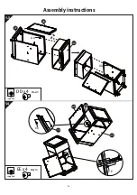
Page 15: ...1 1 1 2 Assembly instructions 15 EE x 16 M4x10 EE not supplied 27 28 29 33 27 17 18 38 FF II DD x 10 M6x14 not supplied FF x 16 D4 not supplied II x 16 M4 DD DD ...

Page 16: ...1 3 1 4 Assembly instructions 16 EE x 4 M4x10 not supplied DD x 4 M6x14 not supplied 26 26 28 13 33 30 27 DD EE EE DD ...

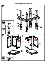
Page 17: ...2 1 2 2 Assembly instructions 17 DD x 10 M6x14 not supplied 16 11 10 12 16 17 38 18 EE DD DD FF II EE x 16 M4x10 not supplied FF x 16 D4 not supplied II x 16 M4 ...

Page 18: ...2 3 2 4 Assembly instructions 18 DD x 4 M6x14 not supplied 9 14 16 DD DD EE x 4 M4x10 not supplied 13 13 11 12 EE EE ...

Page 19: ...3 1 3 2 Assembly instructions 19 BB x 1 19 6 34 30 34 33 19 27 DD CC CC JJ DD x 4 M6x14 CC x 4 M6x12 JJ x 2 6 x 18 mm not supplied ...

Page 20: ...4 1 4 2 Assembly instructions 20 BB x 1 19 7 7 9 19 11 16 6 DD CC CC JJ DD x 4 M6x14 CC x 4 M6x12 JJ x 2 6 x 18 mm not supplied ...

Page 21: ...5 1 5 2 Assembly instructions 21 25 38 23 37 18 KK x 1 DD x 9 M6x14 not supplied DD DD ...

Page 22: ...5 3 6 Assembly instructions 22 21 22 24 44 23 not supplied AA x 2 6 x 12 mm GG AA HH GG x 2 M6x10 not supplied HH x 2 M6 not supplied not supplied A A 25 M6 x 30 D6 M6 ...

Page 23: ...7a Assembly instructions 23 BB x 1 CC x 2 M6x12 not supplied 19 25 19 25 7 M6 x 30 CC ...

Page 24: ...Assembly instructions 24 DD x 2 M6 x 14 not supplied 7b 8a M6 x 30 30 19 34 25 19 33 DD M6 x 30 CC BB x 1 CC x 2 M6x12 not supplied ...

Page 25: ...Assembly instructions 25 DD x 2 M6 x 14 not supplied 8b 9 DD x 8 M6x14 not supplied 7 DD M6 x 30 DD DD 34 20 20 19 19 ...

Page 26: ...Assembly instructions 26 EE x 2 M4x10 not supplied 10 1 not supplied 15 9 10 2 M4 x 10 15 M4 x 10 EE 41 43 42 ...

Page 27: ...Assembly instructions 27 11a 1 11b 2 1 2 3 32 8 3 5 5 ...

Page 28: ...Assembly instructions 28 12a 12b 4 35 35 36 36 4 not supplied not supplied not supplied not supplied M6 M6 M6 x 10 M6 x 10 ...

Page 29: ...CTING LAYOUT Attach the transformer and grounding wire to the cart rear panel with four M4x10 screws and M4 nuts Lamp LED M4 x 10 Red wire Switch Black wire 12V wire Grounding wire Black wire Transformer Red wire LED Switch Grounding wire M4 Halogen bulb wire ...

Page 30: ...attery compartment LED switch Lamp switch Transformer Note The grounding wire and igniter switch wire must be inserted into the positions as figure shown The other wires can be inserted into any other positions Side burner Side valve assembly Electrode wire thick one Grounding wire in black color 1pc Main burner igniter wire in red color 5pcs Igniter switch wire in white color 1pc ...

Reviews: