background image

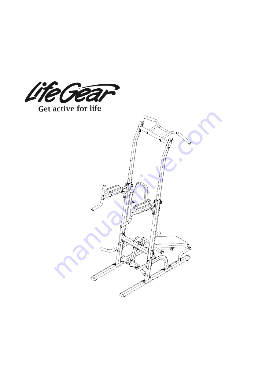
POWER TOWER 

ITEM NO: 77004 


OWNER’S MANUAL 


IMPORTANT: Read all instructions carefully before using this product.    Retain this 
owner’s manual for future reference. 

The specifications of this product may vary from this photo and are subject to change without 
prior notice.

                                                                                                                                                                                                                                                                                                                            2021, March


Summary of Contents for 77004

Page 1: ...NUAL IMPORTANT Read all instructions carefully before using this product Retain this owner s manual for future reference The specifications of this product may vary from this photo and are subject to change without prior notice 2021 March ...

Page 2: ...LE OF CONTENTS WARRANTY 2 IMPORTANT SAFETY INSTRUCTIONS 3 PARTS LIST 4 HARDWARE KIT 1 5 HARDWARE KIT 2 6 EXPLODED VIEW 7 ASSEMBLY INSTRUCTIONS 8 MAINTENANCE 17 ADJUSTMENTS 17 WARM UP AND COOL DOWN ROUTINE 22 ...

Page 3: ...r repairing free of charge any parts which may prove to be defective under normal home use This warranty does not include any damage caused by improper operation misuse or commercial application From the date of purchase the frame is warranted to be free from defects for 1 one year This warranty is offered only to the original owner and is not transferable Proof of purchase is required When orderi...

Page 4: ...o use 8 If you feel any chest pains nausea dizziness or short of breath you should stop exercising immediately and consult your physician before continuing 9 Please wear proper clothes and shoes when using this Power Tower do not wear clothes that might catch any part of the equipment 10 Never exercise in bare feet or socks always wear proper shoes 11 Do not attempt any maintenance or adjustments ...

Page 5: ...8x15 6 011 Adjustable Upper Upright Tube 2 035 Bench Frame 1 012 Backrest 1 036 Bench Support Tube 1 013 Arm Pad 2 037 Ankle Support Tube 1 014 Resistance Band 2 038 Foam Roller Pad Rod Ø25x1 5 1 015 Lock Knob M10x90 2 039 Foam Bench Cushion 800x300x50 1 016 Adjustable Leveler M8x20 6 040 Round End Cap Ø38 4 017 Oval End Cap 40x80x1 5 4 041 Foam Roller Pad 4 018 Upright Tube Bushing 2 042 Pin M10x...

Page 6: ...cs STEP 5 Part 24 M10 4 pcs Part 32 M10x50 4 pcs Part 23 Ø10 8 pcs STEP 4 Part 24 M10 4 pcs Part 31 M10x45 4 pcs Part 23 Ø10 8 pcs STEP 2 Part 24 M10 4 pcs Part 27 M10x60 4 pcs Part 23 Ø10 8 pcs STEP 3 Part 30 M10x20 4 pcs Part 23 Ø10 4 pcs STEP 6 Part 33 Ø8 2 pcs Part 29 Ø8 4 pcs Part 28 M8x85 4 pcs Part 34 M8x15 2 pcs ...

Page 7: ...6 HARDWARE KIT 2 STEP 7 Part 24 M10 3 pcs Part 45 M10x95 2 pcs Part 26 Ø10 2 pcs Part 27 M10x60 1 pc Part 42 1 pc Part 23 Ø10 2 pcs 17 14 17 13 ...

Page 8: ...7 EXPLODED VIEW ...

Page 9: ...wer STEP 1 1 Attach the Upright Tube 2 onto the Base Tube 1 with two Carriage Bolts 22 two Washers 23 and two Nylon Nuts 24 Tighten nylon nuts with the Double Open End Wrench provided Repeat on other Upright Tube 2 and Base Tube 1 Part 22 M10x55 4 pcs Part 23 Ø10 4 pcs Part 24 M10 4 pcs Hardware 17 mm ...

Page 10: ...rt 3 and Base Tube 1 STEP 1 3 Attach the Right Handle 4 onto the Upright Tube 2 with two Nylon Nuts 24 two Hexagon Head Bolts 25 and four Curve Washers 26 Tighten bolts and nylon nuts with two Double Open End Wrenches provided Repeat on other Left Handle 5 and Upright Tube 2 Part 22 M10x55 4 pcs Part 23 Ø10 4 pcs Part 24 M10 4 pcs Hardware 17 mm Part 24 M10 4 pcs Part 25 M10x100 4 pcs Part 26 Ø10 ...

Page 11: ...s with two Double Open End Wrenches provided STEP 3 Attach the Dip Arm 7 onto the Upright Tube 2 with two Hexagon Head Bolts 30 and two Washers 23 Tighten bolts with the Double Open End Wrench provided Repeat on other Dip Arm 7 and Upright Tube 2 Part 24 M10 4 pcs Part 27 M10x60 4 pcs Part 23 Ø10 8 pcs Hardware 17 mm 17 mm Part 23 Ø10 4 pcs Part 30 M10x20 4 pcs Hardware 17 mm ...

Page 12: ... and eight Washers 23 Tighten bolts and nylon nuts with two Double Open End Wrenches provided STEP 5 1 Remove both Lock Knobs 15 from both Upright Tubes 2 Insert both of the Adjustable Upper Upright Tubes 11 into the Upright Tubes 2 Part 23 Ø10 8 pcs Part 24 M10 4 pcs Part 31 M10x45 4 pcs Hardware 17 mm 17 mm ...

Page 13: ...ght Washers 23 Tighten bolts and nylon nuts with two Double Open End Wrenches provided Slide the Adjustable Upper Upright Tubes 11 up or down and settle on the desired height Lock the Adjustable Upper Upright Tubes 11 in place by tightening the Lock Knobs 15 in a clockwise direction Part 23 Ø10 8 pcs Part 24 M10 4 pcs Part 32 M10x50 4 pcs Hardware 17 mm 17 mm ...

Page 14: ... bolts with the Double Open End Wrench provided STEP 6 2 Attach both Arm Pads 13 onto both Dip Arms 7 with four Hexagon Head Bolts 28 and four Curve Washers 29 Tighten bolts with the Double Open End Wrench provided Part 33 Ø8 2 pcs Part 34 M8x15 2 pcs Hardware 14 mm Part 28 M8x85 4 pcs Part 29 Ø8 4 pcs Hardware 14 mm ...

Page 15: ...14 STEP 6 3 Clip the snap hook of the Resistance Band 14 onto loop at the Upright Tube 2 or Base Tube 1 Repeat on other side ...

Page 16: ...tom Cross Bar 6 with two Carriage Bolts 45 two Curve Washers 26 and two Nylon Nuts 24 Tighten nylon nuts with the Double Open End Wrench provided STEP 7 2 Remove the Knob 44 from the Foam Roller Pad Rod 38 Then install the Foam Roller Pad Rod 38 to one of the adjustment holes of the Ankle Support Tube 37 and secure with a Knob 44 ...

Page 17: ...Bench Frame 35 in place using one Nylon Nut 24 one Hexagon Head Bolt 27 and two Washers 23 Tighten bolts and nylon nuts with two Double Open End Wrenches provided Finally insert the Pin 42 into the holes on the Bottom Cross Bar 6 and Bench Frame 35 to lock into position Part 23 Ø10 2 pcs Part 24 M10 1 pc Part 27 M10x60 1 pc Hardware Part 42 1 pc 17 mm 17 mm ...

Page 18: ...lts and nylon nuts on the Power Tower for proper tightness every week Replace missing nylon nuts and bolts Securely tighten loose nylon nuts and bolts Worn or damaged components shall be replaced immediately ADJUSTMENTS Adjusting the Adjustable Leveler Turn the Adjustable Leveler on the Base Tubes as needed to level the Power Tower Adjustable Level Base Tube ...

Page 19: ...irection NOTE Make sure that the Lock Knobs are locked in place before using the pull up bar Adjusting the Foam Roller Pad Rod Remove the Knob and Foam Roller Pad Rod from the Ankle Support Tube Then reinstall the Foam Roller Pad Rod to one of the adjustment holes of the Ankle Support Tube and secure with a Knob that was removed Foam Roller Pad Rod can be adjusted to four positions Lock Knob Pull ...

Page 20: ...t in position by inserting the Pin 42 through the bottom adjustment holes in the Bottom Cross Bar 6 and the holes in the Bench Frame 35 Adjusting the Weight Bench Backrest to Flat Position 2 Pull out the Pin 42 from the top adjustment holes in the Bench Frame 35 and the holes in the Bench Support Tube 36 Weight Bench Backrest Can Be Adjusted to Decline and Flat Positions ...

Page 21: ...rest to Flat Position 3 Fold down the Bench Support Tube 36 and then lock the Bench Support Tube 36 in position by inserting the Pin 42 through the bottom adjustment holes in the Bench Frame 35 and the holes in the Bench Support Tube 36 ...

Page 22: ...ion A Pull out the Pin 42 from the top adjustment holes in the Bottom Cross Bar 6 B Fold up the weight bench and lock in position by inserting the Pin 42 through the top adjustment holes in the Bottom Cross Bar 6 and the holes in the Bench Frame 35 ...

Page 23: ... state at the end of each exercise session A proper cool down slowly lowers your heart rate and allows blood to return to the heart HEAD ROLLS Rotate your head to the right for one count you should feel a stretching sensation up the left side of your neck Then rotate your head back for one count stretching your chin to the ceiling and letting your mouth open Rotate your head to the left for one co...

Page 24: ...Lean against a wall with your left leg in front of the right and your arms forward Keep your right leg straight and the left foot on the floor then bend the left leg and lean forward by moving your hips toward the wall Hold then repeat on the other side for 15 counts TOE TOUCHES Slowly bend forward from your waist letting your back and shoulders relax as you stretch toward your toes Reach as far a...

Reviews: