background image


9

 
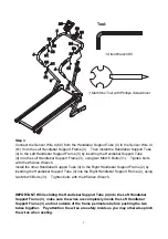
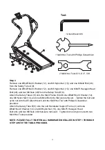
Step 3 

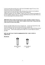
Connect the Sensor Wire II (60) from the Handlebar Support Tube (4) to the Sensor Wire III 
(61) from the Left Handlebar Support Frame (3).    Then install the Handlebar Support Tube 
(4) to the Left Handlebar Support Frame (3) by inserting the Handlebar Support Tube 
(4) into the Left Handlebar Support Frame (3), using two M6x15 Bolts (31).    Tighten bolts 
with the #5 Allen Wrench. 
Install the other Handlebar Support Tube (4) to the Right Handlebar Support Frame (2) by 
inserting the Handlebar Support Tube (4) into the Right Handlebar Support Frame (2), using 
two M6x15 Bolts (31).    Tighten bolts with the #5 Allen Wrench. 


IMPORTANT: While sliding the Handlebar Support Tube (4) into the Left Handlebar 
Support Frame (3), make sure the wires are completely inside the Left Handlebar 
Support Frame (3) and not outside of the frame perimeters before pushing the two 
tubes together.    Pay attention the wires are safely inside as you may otherwise pinch 
the wires when sealing. 

Tool: 

1 Allen Wrench #5 

1 Multi Hex Tool with Phillips Screwdriver

2

3

4

4

5

31

31

31

31

24

24

25

25

26

26

31

31

31

31

61

61

60

60

58

58

28

28

28

28

58

58

60

60

58

58

Summary of Contents for 40120

Page 1: ... 40120 OWNER S MANUAL IMPORTANT Read all instructions carefully before using this product Retain this owner s manual for future reference The specifications of this product may vary from this photo subject to change without notice 2014 Aug ...

Page 2: ...CTIONS 3 OVERVIEW DRAWING 4 PARTS LIST 5 HARDWARE LIST 6 TOOLS 6 ASSEMBLY INSTRUCTIONS 7 OPERATING THE COMPUTER 12 LIFTING UP AND SETTING DOWN THE TREADMILL 14 ADJUSTMENTS 15 LUBRICATION 16 MAINTENANCE 17 TROUBLESHOOTING 17 WARM UP AND COOL DOWN ROUTINE 18 ...

Page 3: ...r repairing free of charge any parts which may prove to be defective under normal home use This warranty does not include any damage caused by improper operation misuse or commercial application From the date of purchase the frame is warranted to be free from defects for 1 one year This warranty is offered only to the original owner and is not transferable Proof of purchase is required When orderi...

Page 4: ...Never wear loose clothing because it could run the risk of getting caught in the magnetic treadmill 7 Keep children and pets away from the equipment while in use 8 Do not use the magnetic treadmill outdoors This magnetic treadmill is for household use only 9 Only one person should be on the magnetic treadmill while in use 10 Keep the magnetic treadmill on a solid level surface with the minimum saf...

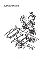
Page 5: ... 12 12 34 34 36 36 38 38 37 37 40 40 41 41 42 42 43 43 44 44 45 45 46 46 12 12 35 35 18 18 50 50 51 51 12 12 13 13 53 53 55 55 54 54 56 56 57 57 29 29 60 60 59 59 61 61 31 31 62 62 8 13 13 12 12 46 46 13 13 12 12 49 49 48 48 47 47 9 63 63 52 52 40 40 41 41 42 42 35 35 46 46 45 45 44 44 12 12 13 13 18 18 32 32 33 33 31 31 19 19 17 17 27 27 4 28 28 27 27 60 60 61 61 37 37 39 39 58 58 58 58 58 58 ...

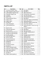
Page 6: ...8x33 2 014 Washer Ø10xØ20x2 0 4 046 Bolt M8x42 3 015 Nylon Nut M10 4 047 Spring Knob M16 1 016 Hexagon Head Bolt M10x40 4 048 Hexagon Head Bolt M8x75 1 017 Hexagon Head Bolt M12x65 2 049 Nut M8 2 018 End Cap 25x50 4 050 Hexagon Head Bolt M8x70 1 019 Washer Ø12xØ24x2 0 2 051 Magnet Bracket 1 020 Round Cap Ø32 2 052 Square Bushing 1 021 Tension Control Knob 1 053 Square End Cap 25x25 1 022 Washer Ø5...

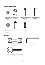
Page 7: ...Tool S13 S17 S19 2 PCS Multi Hex Tool with Phillips Screwdriver 1 PC 14 Washer Ø10xØ20x2 0 4 PCS 15 Nylon Nut M10 4 PCS 16 Hexagon Head Bolt M10x40 4 PCS 17 Hexagon Head Bolt M12x65 2 PCS 19 Washer Ø12xØ24x2 0 2 PCS 24 Bolt M6x35 1 PC 31 Bolt M6x15 6 PCS ...

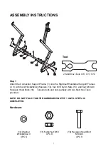
Page 8: ... four M10 Nylon Nuts 15 and four M10x40 Hexagon Head Bolts 16 Tension bolts and nuts partially with two Multi Hex Tools provided NOTE DO NOT FULLY TIGHTEN HARDWARE IN STEP 1 UNTIL STEP 4 IS COMPLETED Hardware Tool 2 Multi Hex Tools S13 S17 S19 3 14 15 15 14 1 16 16 2 14 Washer Ø10xØ20x2 0 4 PCS 15 Nylon Nut M10 4 PCS 16 Hexagon Head Bolt M10x40 4 PCS ...

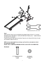
Page 9: ...t the Sensor Wire 56 from the Main Frame 6 to the Sensor Wire III 61 from the Left Handlebar Support Frame 3 NOTE It is recommended that you always use the aid of a second person when assembling the treadmill DO NOT FULLY TIGHTEN HARDWARE IN STEP 2 UNTIL STEP 4 IS COMPLETED Hardware Tool 1 Multi Hex Tool S13 S17 S19 2 3 1 6 19 17 19 17 61 56 17 Hexagon Head Bolt M12x65 2 PCS 19 Washer Ø12xØ24x2 0 ...

Page 10: ...y inserting the Handlebar Support Tube 4 into the Right Handlebar Support Frame 2 using two M6x15 Bolts 31 Tighten bolts with the 5 Allen Wrench IMPORTANT While sliding the Handlebar Support Tube 4 into the Left Handlebar Support Frame 3 make sure the wires are completely inside the Left Handlebar Support Frame 3 and not outside of the frame perimeters before pushing the two tubes together Pay att...

Page 11: ...h the 5 Allen Wrench IMPORTANT While sliding the Handlebar 5 into the Handlebar Support Tubes 4 make sure the wires are not outside of the Handlebar 5 perimeter and pay attention not to pinch the wires when joining Remove two M5x15 Bolts 26 from the Computer 25 Connect the Sensor Wires I 58 from the Handlebar 5 to the wires that come from the Computer 25 Attach the Computer 25 onto the plate of th...

Page 12: ...bolt and nylon nut with the 5 Allen Wrench and the Multi Hex Tool with Phillips Screwdriver provided Attach the Safety Tube B 9 onto the Left Handlebar Support Frame 3 with one Ø8xØ16x2 0 Washer 12 one M8 Nylon Nut 13 one M8x75 Hexagon Head Bolt 48 and two M8 Nuts 49 that were removed Tighten bolt and nylon nut with two Multi Hex Tools provided NOTE PLEASE FULLY TIGHTEN ALL HARDWARE INSTALLED IN S...

Page 13: ...ays SCAN the computer will automatically Alternate the display of TMR SPD DST TOTAL and CAL in sequence and will change the presented image every 4 seconds TMR TIMER Press the MODE key until the screen displays TMR the computer will display your elapsed workout time in minutes and seconds When you start to exercise time starts counting up from 0 00 to 99 59 minutes in 1 second increments You may a...

Page 14: ...start to exercise calories start counting up from 0 0 to 999 9 calories You may also pre set target calories before training when STOP appears on the screen Press the MODE key to select CAL function and then press the SET key to pre set target calories You may press the RESET key to reset the target values of CALORIES to zero The pre set target calories range is from 0 0 to 999 0 calories Once you...

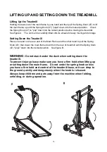
Page 15: ...nd on the rear end of the Main Frame and the other hand to pull the Spring Knob 47 then lower the main frame down from the rear of treadmill until the Spring Knob 47 pops down into the locked position See figure B WARNING Do not stand under the deck when setting down the treadmill To prevent injury please make sure you have a firm hold when lifting up or setting down the main frame Do not undo the...

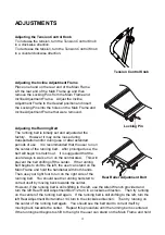
Page 16: ...is suggested that the user always to walk or run on the central area This will prevent the belt shifting off the center If the running belt begins to shift to the left the user can stand on the Main Frame and hold the handlebar with both hands Then use your right foot to run on the right side of the running belt You should see the running belt start to correct itself by moving back towards the cen...

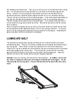
Page 17: ...stment Bolts 1 4 turn in the clockwise direction You should now run on the running belt to determine if the running belt is still slipping Repeating the above procedure until the running belt is not slipping LUBRICATE BELT The treadmill has already been spread with Silicone Oil in advance before leaving the manufacturing plant Silicone oil is without volatility and has gradually permeated through ...

Page 18: ... SOLUTION Remove the computer console and verify the wires that come from the computer console are properly connected to the wires that come from the handlebar SOLUTION Check the batteries are correctly positioned and battery springs are in proper contact with batteries SOLUTION The batteries in the computer console may be dead Replace with new batteries PROBLEM There is no heart rate reading or t...

Page 19: ... state at the end of each exercise session A proper cool down slowly lowers your heart rate and allows blood to return to the heart HEAD ROLLS Rotate your head to the right for one count you should feel a stretching sensation up the left side of your neck Then rotate your head back for one count stretching your chin to the ceiling and letting your mouth open Rotate your head to the left for one co...

Page 20: ...Lean against a wall with your left leg in front of the right and your arms forward Keep your right leg straight and the left foot on the floor then bend the left leg and lean forward by moving your hips toward the wall Hold then repeat on the other side for 15 counts TOE TOUCHES Slowly bend forward from your waist letting your back and shoulders relax as you stretch toward your toes Reach as far a...

Reviews: