background image


5


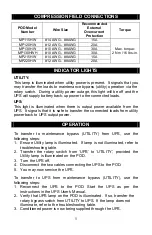
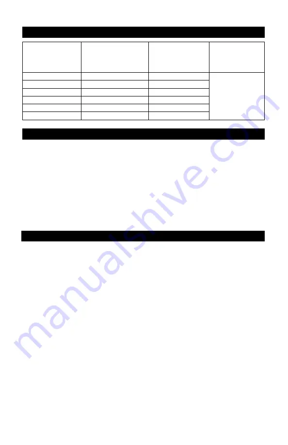
COMPRESSION FIELD CONNECTIONS 


POD


Model 

Number 

Wire Size 

Recommended 

External 

Overcurrent 

Protection 

Torque 

MP115HW 

#14 AWG - #8AWG 

15A 

MP120HW 

#12 AWG - #8AWG 

20A 

MP130HW 

#10 AWG - #8AWG 

30A 

MP130HWH 

#10 AWG - #8AWG 

30A 

MP215HW 

#14 AWG - #8AWG 

15A 

MP220HW 

#12 AWG - #8AWG 

20A 

Max. torque: 

2 Nm / 16 lbs-in. 


INDICATOR LIGHTS 


UTILITY:  
This lamp is illuminated when utility power is present.  It signals that you 
may transfer the loads to maintenance bypass (utility) operation via the 
rotary switch.  During a utility power outage, this light will be off and the 
UPS will supply battery back-up power to the connected loads. 


UPS: 
This light is illuminated when there is output power available from the 
UPS.  It signals that it is safe to transfer the connected loads from utility 
power back to UPS output power. 
 

OPERATION 

 
To transfer to maintenance bypass (UTILITY) from UPS, use the 
following steps: 
1. Ensure Utility lamp is illuminated.  If lamp is not illuminated, refer to 

troubleshooting table. 

2. Transfer the rotary switch from ‘UPS’ to ‘UTILITY’, provided the 

Utility lamp is illuminated on the POD.   

3. Turn the UPS off. 
4. Disconnect the two cables connecting the UPS to the POD.   
5. You may now service the UPS. 
 
To transfer to UPS from maintenance bypass (UTILITY), use the 
following steps: 
1. Reconnect the UPS to the POD. Start the UPS as per the 

instructions in the UPS User's Manual. 

2. Verify that UPS lamp on the POD is illuminated.  If so, transfer the 

rotary bypass switch from UTILITY to UPS.  If the lamp does not 
illuminate, refer to the troubleshooting table. 

3. Conditioned power is now being supplied through the UPS. 

Summary of Contents for MP115HW

Page 1: ...USER MANUAL Power Output Distribution Hardwire POD...

Page 2: ...rs 5 The UPS and POD are designed for data processing equipment Do not plug appliances such as hair dryers heaters vacuum cleaners or electric drills into the UPS output receptacles 6 WARNING Do not m...

Page 3: ...ailable and Utility maintenance bypass During the UPS mode the power is being routed through your UPS system as per Figure 1 Figure 1 Figure 2 During the UTILITY mode of operation the power is being r...

Page 4: ...C 7 Connect the load wiring to the POD terminal block labeled LOAD 8 Open the circuit breakers feeding the input wiring Connect the input wiring to the POD terminal block labeled INPUT Recommended ex...

Page 5: ...at it is safe to transfer the connected loads from utility power back to UPS output power OPERATION To transfer to maintenance bypass UTILITY from UPS use the following steps 1 Ensure Utility lamp is...

Page 6: ...SOLUTION Utility not present Call qualified service personnel to restore power POD input wiring not connected to utility Refer to POD installation section Utility lamp not illuminated Lamp malfunctio...

Page 7: ...es If the POD fails to conform to the above warranty within the two year warranty period Liebert will repair or replace the POD at Liebert s option Repairs or replacements are warranted for the remain...

Page 8: ...than 1000 kVA Integrated systems that provide both environmental and power protection in a single flexible package Monitoring and control on site or remote from systems of any size or location Service...

Reviews: