


USER MANUAL / DL-HD1X4-H2
4
USER MANUAL / DL-HD1X4-H2
5
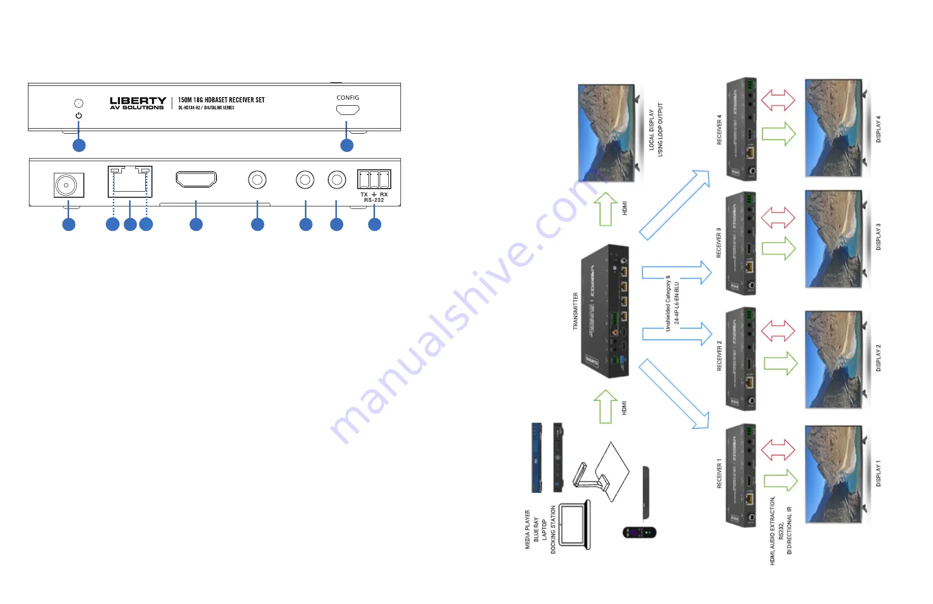
1. LED: Power indicator
2. Female micro USB port: *configuration
3. Female barrel port: DC 24V
4. RJ45 female port: HDBaseT input
from main transmitter
5. LED: Connection Signal Indicator lamp (green)
6. LED: Data signal indicator lamp (orange)
7. Female HDMI port: Output to a display device
8. Female 3.5 jack: Audio output to a audio device
9. IR IN
10. IR OUT
11. 3-Pin phoenix female port. Pass control signals
to or from the main transmitter.
DC 24V
Plug the DC 24V power supply into the unit and connect
the adaptor to an AC outlet. (
Note:
The transmitter can
power the receiver via a CAT cable.)
5.2 HDBaseT Receiver
-5-
HDBT IN
Connect to the HDBT OUTPUT port on the transmitter
with a CAT cable.
HDMI OUT
HDMI output port, connect to HDMI display device such
as TV or Projector with an HDMI cable.
No.
Name
Function Description
1
2
3
Power Indicator
When the receiver is powered on, the power indicator will
be on.
4
CONFIG port
Used for firmware update.
7
DC 24V
Plug DC 24V/1A power supply into the unit and connect
the adapter to an AC outlet.
(
Note:
The HDBaseT receiver also can be powered by the
transmitter via a CAT cable.)
10
11
IR IN
IR OUT
HDMI OUT
DC 24V
HDBT
IN
AUDIO OUT
1
2
3
10
4
11
7
8
9
Data Signal
Indicator lamp
(Orange)
▪ Illuminating: HDMI signal with HDCP.
▪ Flashing: HDMI signal without HDCP.
▪ Dark: No HDMI signal.
Connection
Signal Indicator
lamp (Green)
Data Signal
Indicator lamp
(Orange)
5
6
▪ Illuminating: Transmitter and Receiver are in good
connection status.
▪ Flashing: Transmitter and Receiver are in poor
connection status.
▪ Dark: Transmitter and Receiver are not connected.
▪ Illuminating: HDMI signal with HDCP.
▪ Flashing: HDMI signal without HDCP.
▪ Dark: No HDMI signal.
5
6
Note for extending IR signals: When the angle between the IR receiver and the remote control is ±
45°, the transmission distance is 0-5 meters; when the angle between the IR receiver and the remote
control is ± 90 °, the transmission distance is 0-8 meters.
RECEIVER PRODUCT BREAKDOWN
APPLICATION EXAMPLE


