MODEL :
XB12(XBS12V)
SER
VICE MANU
AL
P/NO : AFN35036924
SEPTEMBER, 2007
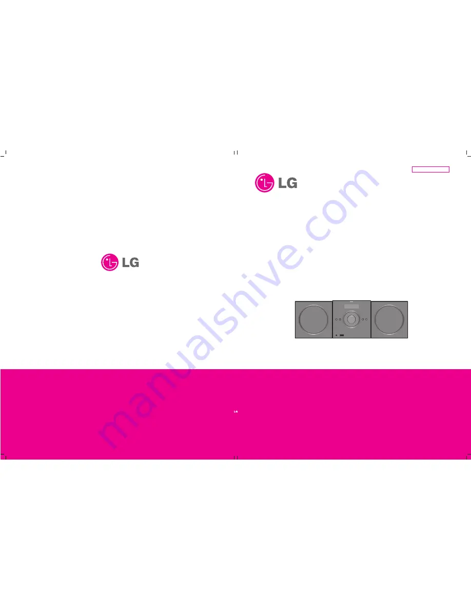
MINI HOME THEATER
SERVICE MANUAL
MODEL : XB12(XBS12V)
Website http://biz.lgservice.com
Internal Use Only
CAUTION
BEFORE SERVICING THE UNIT, READ THE “SAFETY PRECAUTIONS” IN THIS MANUAL.