background image

Installation

21

3

Ins
talla

tion

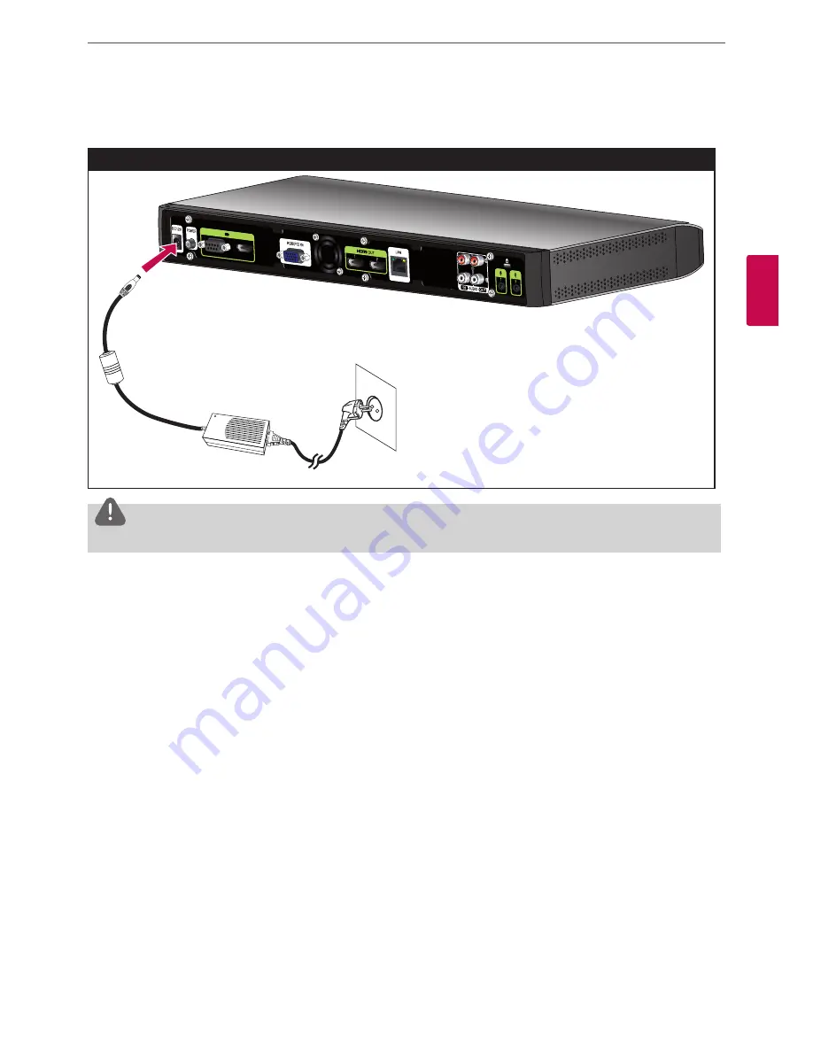
Connecting Power

Connects the power cable as shown in the following illustrations.

Power Connection

 CAUTION

You must use a supported adapter. If you connect another adapter not offered with the system, you may cause a malfunction, failure or fire.

System Connection Check

After all of the connections are completed, follow the steps below to check the system operation.
1.   Turn on the monitor.
2.   Press POWER on the rear of the codec unit. 

System booting will commence. When the booting is completed, the initial configuration menu will be displayed. 
If it is not displayed, check the device connections and make sure the connections are correctly set. 
Now, you can use the system. Do the next configuration. 

Summary of Contents for V5000

Page 1: ...OWNER S MANUAL Video Conference System Please read this manual carefully before operating your set and retain it for future reference MODEL V5000 V5500 VR5010H 1212 V1 5 ...

Page 2: ...user will be required to correct the interference at his own expense A suitable conduit entries knock outs or glands shall be provided in the cable entries of this product in the end user Caution Danger of explosion if battery is incorrectly replaced Replaced only with the same or equivalent type recommended by the manufacturer Dispose of used batteries according to the manufacturer s instructions...

Page 3: ...uld be disposed separately from the municipal waste stream via designated collection facilities appointed by the government or the local authorities 4 The correct disposal of Your old batteries accumulators will help to prevent potential negative consequences for the environment animal and human health 5 For more detailed information about disposal of Your old batteries accumulators please contact...

Page 4: ...hock or serious injury Check for any danger signs such as a wet floor a loosened or damaged power cable or an unstable surface If you encounter any problems ask your dealer for assistance This may cause fire or electric shock Install the system in a place with sufficient air ventilation Keep at least 15 cm between the back of the system and the wall for the cables connected to the system otherwise...

Page 5: ...e any heavy object on the system This may cause system breakdown Install the system on a stable level surface The system may not operate properly Install the system in a place with appropriate moisture and temperature levels Avoid installing the system in a place with high over 40 C or low under 0 C temperature The system can be damaged from a strong impact or vibration Avoid throwing objects with...

Page 6: ...recautions 14 Connection Overview 15 HDMI Connection 16 HD Camera Connection 17 PC Connection 18 Connecting to a Network 19 Connecting an Audio device 20 Connecting a Microphone 21 Connecting Power 21 System Connection Check 22 Using the CODEC UNIT STAND 24 Initial Settings 27 Main Screen Overview 28 System Configuration Menu 29 User Settings 29 General 30 Camera 31 Date Time 32 Admin Settings 32 ...

Page 7: ...y 55 Editing or Deleting an Entry from the Directory 55 Copying an Entry from the Call History 55 Copying an Entry from the Corporate Contact 56 Deleting an Entry from the Call History 56 Sorting and Searching 56 Placing a Call when the Device is Registered in Gatekeeper Server 56 Making a Call when the Device is Registered in SIP Server 57 Using the Camera Control 57 Using Preset function 58 Usin...

Page 8: ...on can be exchanged virtually and immediately saving travel time cost and energy VCS VCS Network Features Convenient and easy graphical user interface H 323 SIP network Internation Standard codec HD video quality 1 280 X 720 30 fps Selectable screen layouts Graphic presentation using Content Sharing Function Administrator password for security One touch call connection using speed dial Graphical d...

Page 9: ...LE D sub CABLE LAN CABLE DC 12 V 1 Video Conference System Quick Setup Guide V5500 4 Optional 3 TV Optional 5 Optional Optional 2 6 HDMI CABLE HDMI CABLE CAMERA CABLE D sub CABLE LAN CABLE DC 12 V 1 Video Conference System Quick Setup Guide V5500 4 Optional 3 TV Optional 5 Optional Optional 2 6 HDMI CABLE HDMI CABLE CAMERA CABLE D sub CABLE LAN CABLE DC 12 V 1 Codec Unit HD Camera Remote Control a...

Page 10: ...ction port Connects the HD camera f HDMI Input port Connects the codec unit and the camera with a HDMI cable g RGB PC IN port Connects the PC with a D sub cable for presentation h Cooling fan i HDMI OUT 1 port Connects the codec unit and the display device with a HDMI cable for main output j HDMI OUT 2 port Connects the codec unit and the display device with a HDMI cable for contents output k LAN ...

Page 11: ...amera and a large object such as a desk d Power input jack Connects to a DC 12 V power supply using proper cables e RJ 45 connection port Connects the codec unit and the HD camera with the supplied camera connection cable It enables power to be provided to the camera and communicate with codec unit The camera is operated without external power supply when the camera and codec unit are connected wi...

Page 12: ...e the user interface place and receive calls and control the far end of the camera connected to the system Before Using the Remote Control Open the battery cover replace batteries 1 5 V AAA matching 2 and 3 ends to the label inside the compartment and then close the battery cover CAUTION Do not mix old and new batteries as this may damage the Remote Control ...

Page 13: ...nable the presentation function Arrow buttons Navigate the menu options Use this button to Pan Tilt control for far end camera OK Confirms menu selections Use this button to return to the previous condition Use this button to set the far end camera preset Use this button to change the screen layout Use this button when you want to make a call Displays the directory menu Use this button when you wa...

Page 14: ...m ensure that the monitor the computer system and other attached devices are turned off Connection Overview The illustration below shows the connections of the system For specific information of each connection refer to the next pages Connection Overview 6 5 1 2 3 4 7 3 Installation ...

Page 15: ...e best image quality If you connect the codec unit to the DVI port of monitor TV using HDMI to DVI converter you should hear the audio through Audio out device because DVI does not support audio interface Please go to Setup Admin System Audio Audio Out and change Audio Out to Line Out The HDMI OUT 2 port is used to output the contents If you connect the HDMI OUT 2 port and use it please go to Setu...

Page 16: ... to suit your view Do not Connect HDMI Out Cable to Camera HDMI Input Port It is recommended to use the camera with the 1280 x 720p60 mode Do not connect Camera Connection Cable RJ 45 with power to D Sub Cable to other device s LAN Jack e g Note book LAN Jack After connecing the Camera Connection Cable properly turn on the Codec Box Otherwise the VCS may cause malfunction Do not hold the camera fo...

Page 17: ...on to the far end user with this connection PC Connection NOTE The D sub Cable D Sub 15 pin female to D sub 15 pin is not included So purchase the cables separately This unit supports 640 x 480 800 x 600 1 024 x 768 1 280 x 720 1 280 x 768 1 280 x 1 024 1 400 x 1 050 and 1 920 x 1 080 and 60Hz for PC output resolutions If the PC screen can not see properly after D sub cable insert or remove from t...

Page 18: ...unit s LAN port to a corresponding port on your router or network using an optional LAN cable with RJ 45 connector Network Connection NOTE When plugging or unplugging the LAN cable hold the plug portion of the cable When unplugging you should hold the lock of the plug portion ...

Page 19: ...AUDIO OUT port of the codec unit as shown in the following illustrations Audio Device Connection NOTE You can transport sound by connecting the AUDIO OUT device to the AUDIO IN Port If you connect the AUDIO IN port and use it please go to Setup Admin System Audio Audio IN and set to Line IN ...

Page 20: ...e between the microphone and the user is about 1 m to 2 m It is recommended to use two of microphone in the auditorium Place two of microphone to fill the sounds whole of conference room and leave space more than 4 m distance between each microphone You can transport voice by connecting the microphone device like as Gooseneck microphone to the AUDIO IN Port If you connect the AUDIO In port and use...

Page 21: ...ailure or fire System Connection Check After all of the connections are completed follow the steps below to check the system operation 1 Turn on the monitor 2 Press POWER on the rear of the codec unit System booting will commence When the booting is completed the initial configuration menu will be displayed If it is not displayed check the device connections and make sure the connections are corre...

Page 22: ...nit stand as shown in the following illustrations 1 Remove the stand connection cover from the codec unit 2 After aligning the position attach the stand connection cover to bottom of the codec unit stand Loosen the fixing screws in bottom of codec unit stand 3 After aligning the position connect the codec unit to the codec unit stand ...

Page 23: ...Installation 23 3 Installation 4 Tighten the fixing screws in bottom of codec unit stand ...

Page 24: ...2 Turn on the unit System booting will commence The logo image will be displayed during the system booting 3 When the booting is complete the initial configuration menu will be displayed 4 Select the language for the text displayed on the screen 4 1 Select the Language option and press OK or The language list is displayed 4 2 Select the language using or and press OK 4 3 Select Next and press OK t...

Page 25: ... incorrectly in Manual Setting you may not be able to connect to calls 5 2 Select Next and press OK to go to the next step or press ll 6 Select the time zone 6 1 Use or to select the time zone and press OK 6 2 Use or to select the country where the device is located and press OK 6 3 Select Next and press OK to go to the next step or press ll 7 Select the one of the network setting options DHCP Sel...

Page 26: ...n SPACE Inserts space at the cursor position 1 a A Changes the input type to numbers small letters or capital letters Numbers Select the numbers small letters or capital letters as selected input type Press the button repeatedly to select the character or symbol as you want When using the virtual keyboard 8 1 Select the virtual keyboard icon and press OK The virtual keyboard input menu displayed 8...

Page 27: ...ation NOTE Additionally refer to the on screen instructions for each option s setting If you want to move to the previous option settings select Prev and press OK or press l Main Screen Overview a b c d e f g h i j k l m n o p ...

Page 28: ...ress Displays the current IP address of the unit j Text Input Field Enter the dial numbers or IP address manually k Call Button Use this button when you want to make a call l Menu Hide You can hide the user interface elements and you can show the user interface element other remote key m Camera Control You can select the appropriate view area n Call You can make a call from text input field addres...

Page 29: ...ce and do not wish to be disturbed by incoming calls Screen Saver When your system is idle during the selected time it will be activated and the LG logo will be displayed on the monitor An incoming call or pressing any button on the remote control automatically invokes the system Language Select a language for the setup menu and information display Outgoing Protocol Select the protocol to use when...

Page 30: ...y adjusting the camera brightness 1 Press OK and adjust brightness using the left or right arrow button 2 Press OK to confirm the setting Sharpness Select the sharpness level for the camera 1 Press OK and adjust sharpness using the left or right arrow button 2 Press OK to confirm the setting Focus Mode Select the camera focus mode Trigger Auto The focus function is activated when using the PTZ fun...

Page 31: ...40 Time Server Address Enter the IP address or hostname of the time server This option is activated when you set to manual in the Time Server setting menu Date Format Select the display format for date Daylight Saving Set the daylight savings time 1 Press OK and then the daylight savings time setting menu will be displayed 2 Mark up to set the daylight savings function 3 Set the daylight savings s...

Page 32: ...splayed So you can hang up or continue the call Maximum Bandwidth Select the maximum amount of network bandwidth to use for video call H 323 This unit supports the H 323 protocol for placing and receiving video and voice calls This is used when a gatekeeper function is attempted H 323 Name Enter the name of the device used when making calls with H 323 with the alphabet numbers and special characte...

Page 33: ...use the H 460 standard for NAT and firewall traversal GateKeeper Address Enter the IP address of the primary H 323 gatekeeper GateKeeper Port Enter the port number of the primary H 323 gatekeeper NOTE You can check the registered status in the Server Status menu of the system information window Security function may not be supported in specific countries When both Near End user and Far End user ar...

Page 34: ...u set to On the username password register server address register server port proxy server address and proxy server port options are enabled to set it User Name Enter the SIP server authorization username Password Enter the SIP server authorization password Register Server Address Enter the hostname or IP address of the SIP register server Register Server Port Enter the IP port number of the SIP ...

Page 35: ...of the Service ToS preference If you select this option the IntServToS option is enabled to set it IntServToS Select IP Type of Services This helps a router select a router path when multiple paths are available IntServAudio Enter the priority of Audio for Intserv Quality of Service QoS Range 0 7 IntServVideo Enter the priority of Video for Intserv Quality of Service QoS Range 0 7 IntServData Ente...

Page 36: ...s assigned automatically If you set to this the IP address subnet mask gateway main DNS and sub DNS options are dimmed STATIC Select this option when you set the network configuration manually IP Address Enter the static IP address of the device Subnet Mask Enter the subnet mask IP address Gateway Enter the default gateway IP address Main DNS Enter the Primary domain name server that translates th...

Page 37: ...ystem Fixed Port You can fix the TCP and UDP port range If you set to On the TCP port and UDP port options are enabled TCP Port Enter the lowest highest number in the reserved range of the TCP port numbers Minimum range of port is 1 UDP Port Enter the lowest highest number in the reserved range of the UDP port numbers Minimum range of port is infinite Service Web Server If you set to On you can co...

Page 38: ...munity in which you want to enable this system e g lgecommunity or public LDAP LDAP is the ability to read registered address books in the LDAP server If you connect to an LDAP server you can confirm in corporate contact tab in directory LDAP Disable Not used with this function Enable Selects when the LDAP server allows access to this device Hostname Enter the host name or IP address of your LDAP ...

Page 39: ... Select this option to 802 1x user authentication If you select this option identity password and EAP method options are enabled Identity Enter the identity name given to you by your IT administrator This specifies the system s identity used for 802 1X authentication Password Enter the password given to you by your IT administrator This specifies the system s password used for 802 1X authenticatio...

Page 40: ...client key files to the web service of your system as shown in the picture below When User Use EAP PEAP 1 If you use EAP PEAP you must receive a ca pem file from the 802 1x network manager 2 Upload the ca pem file to the web service of your system as shown in the picture below After Setting 802 1x 1 When you finish these settings confirm that you can see your IP on the main screen 2 Perform a ping...

Page 41: ... Manual mode to set the value of Speed Duplex When Assignment is set to Auto the highest priority is 100 Mbps If you set to the Manual mode the Speed and Duplex options are enabled Speed Select the speed that your network uses Duplex Select duplex mode that your network uses ...

Page 42: ... echo function to ON or OFF On Select when you want to turn on the echo cancellation Off Select when you want to turn off the echo cancellation Audio Out Select the location for audio output during calls HDMI Audio is output via the connected HDMI device Line Out Audio is output via the connected audio device RingTone Select the volume level of the ring tones Off The ring tone volume is off Small ...

Page 43: ...ou can initialize the configuration of the setup menu 1 Select Reset and press OK The warning window is displayed 2 Select OK and press OK The system will be initialized and restarted Factory Reset You can reset the system to its original factory settings 1 Select Reset and press OK The warning window is displayed 2 Select OK and press OK The system will be reset to factory default settings and re...

Page 44: ...on After the configuration setup you can view the condition of the system Press INFO to display the system information System Status You can view the information of the current system status and configuration Video You can check the video condition ...

Page 45: ...etwork connection issues with your system using the ping and traceroute utilities in Network Utility 1 Select the IP Address field 2 Press OK to enter a value If necessary use 1 a A to change the method of text entry for text fields or select the keyboard icon to display the virtual keyboard After entering a value hide the keyboard if you used it to enter the value and press OK to exit the field 3...

Page 46: ...46 Installation 3 Installation Server Status You can view the server status ...

Page 47: ...he image appears too dark you may need to adjust the room lighting or camera brightness and white balance and check the Shutter menu Placing a Call You can place a call from your system to another VCS Begin a call in one of the following ways Placing a Call Manually You can place a call by entering the IP address manually 1 Select the Text input field and press OK 2 Enter an IP address or dial num...

Page 48: ...2 Follow steps 1 4 described in Placing a Call Manually NOTE You can add up to 3 users Placing a Call from the Call History The list of the Call History stores up to 50 recently dialed phone numbers The oldest entry in the list is automatically removed when the system receives a call or places a call after the maximum number of entries has been reached The last call placed always appears first on ...

Page 49: ...ncoming call Manual If you select this option you must manually answer incoming calls If your system is configured for answering calls manually choose one of the following options when an incoming call arrives Select Pickup and press OK to accept the call Select Reject and press OK to reject the call Do not disturb me If you select this option you can block the all of the call from the other syste...

Page 50: ...all Refer to below table for mute condition Activate Deactivate Symbol On the screen On the microphone Managing Video Layout During a call video from the connected caller appears in your monitor You can change the screen layout of near and far end video Understanding Screen Layouts Typically screen layouts appear as the following types A far end participant or a presentation appears on the left wi...

Page 51: ... the system with D sub cable see page 16 2 Let out the video out correctly on your PC e g Fn Function F7 LG laptop only or Dual monitor setting 3 Select the near end video and press VIDEO SOURCE The Video Source Setting window is displayed 4 Press OK and select VGA Input option and then press OK 5 Select OK and press OK The PC screen is displayed on the near end video window ...

Page 52: ...mera screen will be displayed in one monitor or TV If you set to Second display option to ON Content and Main Camera screen will be displayed on two monitors or TV connected to each HDMI Port separately The screen shows below table as the Video Source Setting of near end camera Video Source Setting HDMI OUT 1 HDMI OUT 2 Main Camera 1 Camera Screen Contents Screen VGA Input Contents Screen Camera S...

Page 53: ...ation Packet loss can be caused by a number of factors including signal degradation over the network medium oversaturated network links corrupted packets rejected in transit faulty networking hardware maligned system drivers or network applications or normal routing routines Video Audio jitter Shows the variation in milliseconds in the time between packets arriving caused by network congestion tim...

Page 54: ... method of text entry for text fields or select the keyboard icon to display the virtual keyboard After entering a value hide the keyboard if you used it to enter the value and press OK to exit the field 4 Use the arrow buttons to select the Address field Press OK to enter a value If necessary use 1 a A to change the method of text entry for text fields or select the keyboard icon to displayed the...

Page 55: ...e control or select Directory on the main screen and press OK to access the directory 2 Select the entry you wish to edit and press lll The Edit Directory window is displayed If you delete the entry select entry and press llll or DEL The Delete Contact window is displayed and you select OK and press OK on the remote controller 3 Modify values in the Edit Directory Entry dialog Copying an Entry fro...

Page 56: ... gatekeeper server 1 You must confirm registered far site name in gatekeeper server 2 Select the text input field and press OK 3 Enter a registered far site name Use 1 a A to change the method of text entry for text input field 4 After entering a value press OK is selected automatically 5 Press OK again to place a call The call status dialog box is displayed NOTE If you want to cancel the call pre...

Page 57: ...setting you should select the site you want to set the preset during the call 2 Press PRESET on the remote control The preset window is displyed 3 Select the preset number you want to save using the left or right arrow button 4 Press OK to save the preset 5 Press BACK to exit the preset setting or 1 Press PRESET on the remote control The preset window is displayed 2 Select the Select Site icon and...

Page 58: ...n the screen NOTE You can confirm this snapshot information in the Call History You can save entry with this snapshot information in the My Contact list Using Power Off Press the button on the remote control more than 3 seconds the Power Off window is displayed Click OK to turn off the software Press the button again to power on the software If you power on the software the screen returns to norma...

Page 59: ...e DDNS setup menu of the VCS 3 Press ENTER on the keyboard and then the LG VCS Web service login page will be displayed 4 Select the ID and enter the password The default password is lge123 for Administrator and lge456 for User 01 to User 04 NOTE Up to 5 users can connect to the Web Service When you close web service you should click logout button on the right up side of web page If you log in and...

Page 60: ...m again If setup message still appears despite installation VLC Player might not be the recommended version Click the Click Here on the If VLC is installed already Click Here message and then check the installation guide When you find this message VLC might not be installed please Click here to install it to avail monitoring click the Click here to move the setup page and install the VLC program I...

Page 61: ...is halted temporarily and will be restarted with new recording file Video Clip Information is like as below Items Information Video Codec MPG2 Ffmpeg Decorder Input Output Type MPG2 0 bits YUV2 16 bits Input Output Size 704 x 576 1 22 1 Minimum Disk Space for recording 4 GB Video Player VLC media player See page 60 Minimal H W Requirement to use the web recording function Intel Core 2 Duo CPU P880...

Page 62: ... system upgrade status bar is displayed 8 After upgrading is complete a confirmation window will be displayed Click OK and the system will be rebooted 9 If you use the web service after updating access the web service again as IP address after the system is rebooted NOTE Before updating reboot the VCS Otherwise update may not work properly Uploading the Certification File 1 Follow steps 1 3 descri...

Page 63: ... Click Save 5 Select the folder and modify the export file name 6 Click Save Importing the Address Book 1 Follow steps 1 4 described in Login the web service 2 Select the Directory tab 3 Click the Import File menu The Import CSV File window is displayed 4 Find and open the address book file and then click OK The imported address will be added and you can see the added address on the list 5 Import ...

Page 64: ... camera icon in main screen The image is not visible Check that the camera cable is connected correctly on device You can confirm camera connection status as camera icon in main screen If you connect Camera Input HDMI Cable to HDMI TV or Monitor or If you connect Codec Box s HDMI Out Cable to Camera HDMI Input Port it can cause malfunction Color noise or not visible So Check HDMI Cables Connection...

Page 65: ... with each site s IP operators that your video UDP traffic is NOT being blocked by IPS Intrusion Protection System Check the remote user s VCS video capability What video resolution is supported HD 720p SD 720x480 What video codec is supported H 264 H 263 H 264HP Can not see the PC screen after pressing VIDEO SOURCE or PRESENTATION Check that the D sub cable is connected properly between the PC an...

Page 66: ... to the source code all referred license terms warranty disclaimers and copyright notices are available for download LG Electronics will also provide open source code to you on CD ROM for a charge covering the cost of performing such distribution such as the cost of media shipping and handling upon email request to opensource lge com This offer is valid for three 3 years from the date on which you...

Page 67: ...cus Auto View range 6 degree to 72 degree 11 degree to 72 degree Pan Tilt range 100 20 30 FOV 72 Backlight WDR YES Min Illumination 15 lx F1 6 with 50 IRE IR Detector YES interface HDMI D Sub to RJ45 for Signal and Power Audio Standard G 711 G 722 G 722 1 G 722 1C Features Ring tone Full duplex for natural conversations Echo cancellation for echo free calls Automatic noise reduction Automatic gain...

Page 68: ...a Web Recording Web Recording Security Secure password authentication Ability to disable HTTP services H 235 AES encryption support including strict compliance SSH and Telnet services IEEE 802 1x support Kensington Security Slot Environmental Data Camera Operating temperature 0 C 32 F to 40 C 104 F Operating Humidity 15 to 80 non condensing Storage temperature 20 C 4 F to 60 C 140 F Storage humidi...

Page 69: ...CA Camera Input 1 x HDMI D Sub Video In 1 x VGA HDMI Video Out 2 x HDMI 480p 720p 2nd Video Out supports the contents only LAN Port 1 x RJ 45 10 100 1000 Mbps Power 1 x DC Input MicPod 3 5 mm Micpod with Mute Power Adaptor Type model FSP060 DBAC1 Rating Input 100 240 V 50 60Hz 1 5 A Output DC 12 V Maximum 5 0 A NOTE AES function may not be supported in specific countries ...

Page 70: ......

Reviews: