background image

- 4 -

CAUTION: 

Before servicing receivers covered by this service

manual and its supplements and addenda, read and follow the

SAFETY PRECAUTIONS

on page 3 of this publication.

NOTE: 

If unforeseen circumstances create conflict between the

following servicing precautions and any of the safety
precautions on page 3 of this publication, always follow the
safety precautions. Remember: Safety First.

General Servicing Precautions

1.  Always unplug the receiver AC power cord from the AC

power source before;
a.  Removing or reinstalling any component, circuit board

module or any other receiver assembly.

b.  Disconnecting or reconnecting any receiver electrical plug

or other electrical connection.

c. Connecting a test substitute in parallel with an electrolytic

capacitor in the receiver.

CAUTION: 

A wrong part substitution or incorrect

polarity installation of electrolytic capacitors may result
in an explosion hazard.

d.  Discharging the picture tube anode.

2.  Test high voltage only by measuring it with an appropriate

high voltage meter or other voltage measuring device (DVM,
FETVOM, etc) equipped with a suitable high voltage probe.
Do not test high voltage by "drawing an arc".

3.  Discharge the picture tube anode only by (a) first connecting

one end of an insulated clip lead to the degaussing or kine
aquadag grounding system shield at the point where the
picture tube socket ground lead is connected, and then (b)
touch the other end of the insulated clip lead to the picture
tube anode button, using an insulating handle to avoid
personal contact with high voltage.

4.  Do not spray chemicals on or near this receiver or any of its

assemblies.

5. Unless specified otherwise in this service manual, clean

electrical contacts only by applying the following mixture to
the contacts with a pipe cleaner, cotton-tipped stick or
comparable nonabrasive applicator; 10% (by volume)
Acetone and 90% (by volume) isopropyl alcohol (90%-99%
strength)

CAUTION: 

This is a flammable mixture.

Unless specified otherwise in this service manual, lubrication
of contacts in not required.

6.  Do not defeat any plug/socket B+ voltage interlocks with

which receivers covered by this service manual might be
equipped.

7.  Do not apply AC power to this instrument and/or any of its

electrical assemblies unless all solid-state device heat sinks
are correctly installed.

8.  Always connect the test receiver ground lead to the

receiver chassis ground before connecting the test receiver
positive lead.
Always remove the test receiver ground lead last.

9. 

Use with this receiver only the test fixtures specified in this
service manual.

CAUTION: 

Do not connect the test fixture ground strap to

any heatsink in this receiver.

Electrostatically Sensitive (ES) Devices

Some semiconductor (solid state) devices can be damaged
easily by static electricity. Such components commonly are
called 

Electrostatically Sensitive (ES) Devices.

Examples of

typical ES devices are integrated circuits and some fieldeffect

transistors and semicounductor "chip" components. The
following techniques should be used to help reduce the
incidence of component damage caused by static by static
electricity.
1.  Immediately before handling any semiconductor component

or semiconductor-equipped assembly, drain off any
electostatic charge on your body by touching a known earth
ground. Alternatively, obtain and wear a commercially
available discharging wrist strap device, which should be
removed to prevent potential shock reasons prior to
applying power to the unit under test.

2.  After removing an electrical assembly equipped with ES

devices, place the assembly on a conductive surface such as
aluminum foil, to prevent electrostatic charge buildup or
exposure of the assembly.

3.  Use only a grounded-tip soldering iron to solder or unsolder

ES devices.

4. Use only an anti-static type solder removal device. Some

solder removal devices not classified as "anti-static" can
generate electrical charges sufficent to demage ES devices.

5.  Do not use freon-propelled chemicals. These can generate

electrical charges sufficient to damage ES devices.

6.  Do not remove a repalcement ES device from its protective

package until immediately before you are ready to install it.
(Most replacement ES devices are packaged with leads
electrically shorted together by conductive foam, aluminum
foil or comparable conductive material).

7.  Immediately before removing the protective material from

the ieads of a replacement ES device, touch the protective
material to the chassis or circuit assembly into which the
device will be installed.

CAUTION:

Be sure no power is applied to the chassis or

circuit, and observe all other safety precautions.

8.  Minimize bodily motions when handling unpackaged

replacement ES devices. (Otherwise harmless motion such
as the bruching together of your clothes fabric or the lifting
of your foot from a carpeted floor can generate static
electricity sufficient to damage an ES device.)

General Soldering Guidelines

1.  Use a grounded-tip, low-wattage soldering iron and

appropriate tip size and shape that will maintan tip
temperature within the range or 500

c

F to 600

c

F.

2.  Use an appropriate gauge of RMA resin-core solder

composed of 60 parts tin/40 parts lead.

3.  Keep the soldering iron tip clean and well tinned.
4.  Thorohly clean the surfaces to be soldered. Use a mall

wirebristle (0.5 inch, or 1.25cm) brush with a metal handle.
Do not use freon-propelled spray-on cleaners.

5.  Use the following unsoldering technique

a.  Allow the soldering iron tip to reach normal temperature.

(500

c

F to 600

c

F)

b.  Heat the component lead until the solder melts.
c.  Quickly draw the melted solder with an anti-static,

suction-type solder removal device or with solder braid.

CAUTION:

Work quickly to avoid overheating the

circuiboard printed foil.

6.  Use the following soldering technique.

a.  Allow the soldering iron tip to reach a normal

temperature (500

c

F to 600

c

F)

b.  First, hold the soldering iron tip and solder the strand

against the component lead until the solder melts.

SERVICING PRECAUTIONS

Summary of Contents for RT-15LA31

Page 1: ...TION BEFORE SERVICING THE CHASSIS READ THE SAFETY PRECAUTIONS IN THIS MANUAL CHASSIS ML 012A MODEL RT 15LA31 website http biz LGservice com e mail http www LGEservice com techsup html Jun 2002 Printed in Korea P NO 3828VD0108U ...

Page 2: ...NTS Contents 2 Safety Precautions 3 Servicing Precautions 4 Description of Controls 6 Adjustment Instruction 9 Troubleshooting 15 Exploded View 16 Exploded View Parts List 17 Replacement Parts List 18 SVC Sheet ...

Page 3: ...perform an AC leakage current check on the exposed metallic parts of the cabinet such as antennas terminals etc to be sure the set is safe to operate without damage of electrical shock Leakage Current Cold Check Antenna Cold Check With the instrument AC plug removed from AC source connect an electrical jumper across the two AC plug prongs Place the AC switch in the on positioin connect one lead of...

Page 4: ...s are integrated circuits and some fieldeffect transistors and semicounductor chip components The following techniques should be used to help reduce the incidence of component damage caused by static by static electricity 1 Immediately before handling any semiconductor component or semiconductor equipped assembly drain off any electostatic charge on your body by touching a known earth ground Alter...

Page 5: ...the corresponding lead on the circuit board 4 Securely crimp each connection and solder it 5 Inspect on the circuit board copper side the solder joints of the two original leads If they are not shiny reheat them and if necessary apply additional solder Fuse and Conventional Resistor Removal Replacement 1 Clip each fuse or resistor lead at top of the circuit board hollow stake 2 Securely crimp the ...

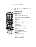
Page 6: ...and selects a programme 3 MENU or INDEX selects a menu selects an index page in the teletext mode only TELETEXT models 4 D D E E Programme Up Down selects a programme or a menu item switches the set on from standby F F G G Volume Up Down adjusts the volume adjusts menu settings OK accepts your selection or displays the current mode 5 Q VIEW returns to the previously viewed programme 6 TELETEXT BUT...

Page 7: ...In teletext mode the PR Q VIEW and LIST buttons are used for teletext functions Battery installation The remote control handset is powered by two AAA type batteries To load the batteries turn the remote control handset over and open the battery compartment Install two batteries as indicated by the polarity symbols and marked inside the compartment Note To avoid damage from possible battery leakage...

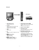
Page 8: ...dby 7 POWER STANDBY INDICATOR r r illuminates brightly when the set is in standby mode dims when the set is switched on 8 REMOTE CONTROL SENSOR 9 HEADPHONE SOCKET Connect the headphone plug to this socket 10 AUDIO VIDEO IN SOCKETS AV Connect the audio video out sockets of exter nal equipment to these sockets S VIDEO AUDIO IN SOCKETS S Video Connect the video out socket of an S VIDEO VCR to the S V...

Page 9: ... minutes preliminarily before adjustment if there is no specific designation Heat Run must be performed with the full white signal or TV noise signal in the internal part of the set The time for Heat Run can be changed owing to production plan 3 PC Input Mode Adjustment 3 1 Required Test Equipment 1 A pattern generator being in proportion to VG819 Pattern of 11 tones 2 A Service remote control 3 2...

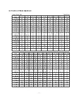
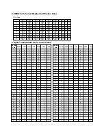
Page 10: ...66 600 66 6 POS 23 37 Mode H_Total H_Display H_Blanking H_Sync H Polarity H_Bp H_Fp H Freq KHz Clk MHz V_Total V_Display V_Blanking V_Sync V Polarity V_Bp V_Fp SVGA 75 1056 800 256 80 POS 160 16 46 875 49 5 625 600 25 3 POS 21 1 SVGA 85 1048 800 248 64 POS 152 32 53 674 56 25 631 600 31 3 POS 27 1 XGA 60 1344 1024 320 136 NEG 136 160 48 363 65 0 806 768 38 6 NEG 29 3 XGA 70 1328 1024 304 136 NEG 1...

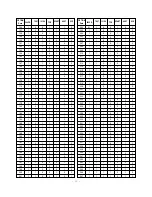
Page 11: ...0 0 0 0 0 0 0 0 0 0 0 0 0 0 0 0 0 0 0 0 0 0 0 0 0 0 0 0 0 0 0 0 0 0 0 0 0 0 0 0 0 0 0 0 0 0 0 0 0 0 0 0 0 0 0 0 0 0 0 0 0 0 0 0 0 0 0 0 0 0 0 0 0 1 1 1 1 1 1 1 1 1 1 1 1 1 1 1 1 0 0 0 0 1 1 1 1 0 0 0 0 1 1 1 1 0 0 0 0 1 1 1 1 0 0 0 0 1 1 1 1 0 1 2 3 0 1 2 3 0 1 2 3 0 1 2 3 0 1 2 3 0 1 2 3 0 1 2 3 0 1 2 3 SCART 0 0 0 0 0 0 0 0 1 1 1 1 1 1 1 1 0 0 0 0 0 0 0 0 1 1 1 1 1 1 1 1 OPTION Data 200PR TEXT I...

Page 12: ... 0 0 0 0 1 1 1 1 1 1 1 1 0 0 0 0 0 0 0 0 1 1 1 1 1 1 1 1 0 0 0 0 0 0 0 0 1 1 1 1 1 1 OPTION Data 200PR TEXT I II SV TOP A2 ST SYS 110 111 112 113 114 115 116 117 118 119 120 121 122 123 124 125 126 127 128 129 130 131 132 133 134 135 136 137 138 139 140 141 142 143 144 145 146 147 148 149 150 151 152 153 154 155 0 0 0 0 0 0 0 0 0 0 0 0 0 0 0 0 0 0 1 1 1 1 1 1 1 1 1 1 1 1 1 1 1 1 1 1 1 1 1 1 1 1 1 ...

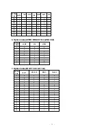
Page 13: ... 0 1 SCART 1 1 1 1 0 0 0 0 0 0 0 0 1 1 1 1 1 1 1 1 0 0 0 0 0 0 0 0 1 1 1 1 1 1 1 1 0 0 0 0 0 0 0 0 1 1 OPTION Data 200PR TEXT I II SV TOP A2 ST SYS 202 203 204 205 206 207 208 209 210 211 212 213 214 215 216 217 218 219 220 221 222 223 224 225 226 227 228 229 230 231 232 233 234 235 236 237 238 239 240 241 242 243 244 245 246 247 01 1 1 1 1 1 1 1 1 1 1 1 1 1 1 1 1 1 1 1 1 1 1 1 1 1 1 1 1 1 1 1 1 1...

Page 14: ... 1 1 1 1 1 1 1 6 Option2 data ACMS BBACK 1bit LANG 3bit 7 Option3 data IIC AFT CH AU 1bit OPTION Data ACMS VOL 0 1 2 3 4 5 6 7 0 0 0 0 1 1 1 1 0 0 1 1 0 0 1 1 HIDEV 0 1 0 1 0 1 0 1 OPTION Data IIC AFT MD SAVE 0 1 2 3 4 5 6 7 8 9 10 11 12 13 14 15 0 0 0 0 0 0 0 0 1 1 1 1 1 1 1 1 0 0 0 0 1 1 1 1 0 0 0 0 1 1 1 1 MONO CH AUS 0 0 1 1 0 0 1 1 0 0 1 1 0 0 1 1 0 1 0 1 0 1 0 1 0 1 0 1 0 1 0 1 ...

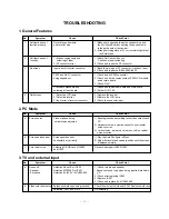
Page 15: ...r recheck them 2 Check and repair the IC804 805 SI4925 P502 and Pin 21 connector 1 Check and fix P902 connector being slipped out 2 Check and fix the components at P902 LCD module and at main board 3 Check Pin21 Cracked components and 1 Check and repair tuner board and main board soldering at tuner board 2 Solder Q101 102 4 Dark screen 1 Defective LCD lamp 1 Replace the inverter 2 Defective invert...

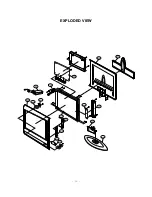
Page 16: ... 16 EXPLODED VIEW P801 112 540 500 541 300 121 120 A4 400 430 420 410 530 310 560 330 ...

Page 17: ...ONE 410 4811V00015A BRACKET ASSY MAIN 420 4950V00063B METAL HINGE FIXER SUS304 15LA30 430 3581V00033A DOOR ASSEMBLY 500 3141VMNC22C CHASSIS ASSY MAIN ML012A 3141VMNC22D CHASSIS ASSY MAIN ML012A 530 6871VSMA12A PWB PCB ASSY CTL ASSY RT 15LA3 540 6633VA0003K INVERTER ASSY 12VOLT VOLT ECT ALPS4LAMP 541 4814V00228A SHIELD CASE INVERTER ET C 32X203 400 560 6871VSMA13F PWB ASSY POWER ML012A RT 15LA31 P8...

Page 18: ... IC604 IC605 IC801 IC901 IC902 IC903 IC904 IC905 IC906 IC907 IC908 IC909 IC914 Q1 Q2 D1 D2 D601 D602 D801 D802 D805 LD1101 ZD101 IC802 IC803 IC804 IC805 IC913 Q3 Q4 0IZZVC0042C 0IAL241610B 0IFA752700A 0IMCRNS002A 0IAL242110A 0IPH740800M 0IIT323000D 0IHY100100A 0IMCRMN011B 0ISA428200A 0IKE704200J 0IMCRFA009A 0IMCRFA008A 0ITC786000A 0IMCRG2004B 0IPH806520A 0IPH743730E 0IZZVC0041C 0IZZVC0041D 0ISS416...

Page 19: ...47UF MVG 16V M SMD R TP LOCA NO PART NO DESCRIPTION C946 C970 C1101 JA201 JA203 JA204 JA205A JA205B JA206 L102 L802 L803 L1101 T801 JA202 P1 P2 P3 P202 P601 P602 P1101 P1103 R219 R220 R413 R953 RA901 RA902 RA903 RA904 RA905 RA906 RA907 RA908 RA909 RA910 RA911 RA912 RA926 RA927 RA928 RA929 RA930 0CE476SF6DC 0CE107SF6DC 0CE107DD618 6612VAH001A 6613V00008F 6612VJH008D 380 336E 380 336F 6612VCH003B 0L...

Page 20: ...S2012 080JT CERATEC 2012MM FILTER HB 1S2012 080JT CERATEC 2012MM FILTER HH 1M3216 501 CERATEC 3216MM R FILTER HB 1S2012 080JT CERATEC 2012MM FILTER HB 1S2012 080JT CERATEC 2012MM FILTER HB 1S2012 080JT CERATEC 2012MM FILTER HB 1S2012 080JT CERATEC 2012MM FILTER HH 1M3216 501 CERATEC 3216MM R FILTER HH 1M3216 501 CERATEC 3216MM R FILTER HB 1S2012 080JT CERATEC 2012MM FILTER HH 1M3216 501 CERATEC 32...

Page 21: ...P No 3854VA0097A S1 1 2 2002 06 12 ...

Page 22: ...P No 3854VA0097A S1 2 2 2002 06 12 ...

Page 23: ...PRINTED CIRCUIT BOARD MAIN TOP CONTROL TOP CONTROL BOTTOM MAIN BOTTOM P No 3854VA0097A S2 2002 06 20 ...

Page 24: ...SVC SHEET 3854V A0097A S ...

Reviews: