8 AHU Control Kit / EEV Kit
Part Description
EEV Kit(PRLK048A0)
1
2
5
3
4
4
8
7
6
1
2
3
4
5
6
7
8
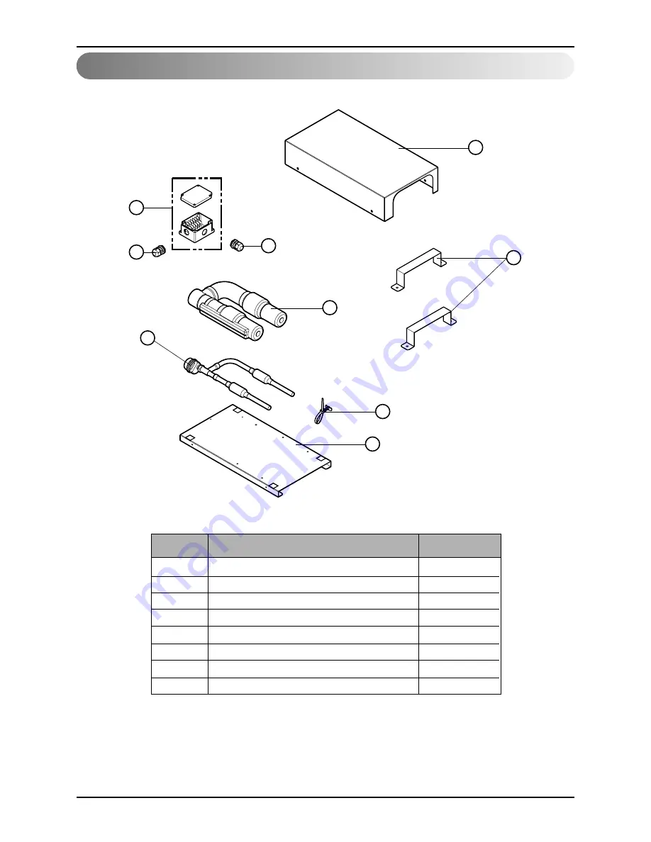
Panel upper
Bracket
Terminal box
Cable gland
Insulator tube
EEV assembly (EEV, Strainer, Tube)
Support tie wrap
Panel base
1
2
1
2
1
1
1
1
No.
Part Name
Quantity(EA)


