


Installation Manual
7
Installation Guide
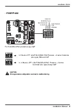
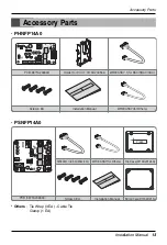
Installation Steps (PHNFP14A0/PSNFP14A0)
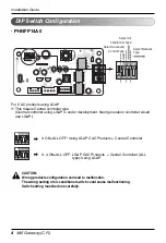
1. Select DIP Switch Configuration(Refer page 8 ~ 10)
2.
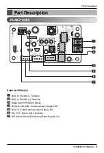
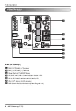
Connect RS-485 BUS_A(+), BUS_(B)(-) with other network products (ex.
Simple Central Controller , ACP.....)
3. Connect CN_OUT with Indoor Unit by the cable (provided)
4. Check the Communication Status LED
- LED1G(Red)
• OK operation : LED blinks for 5 times and then gets OFF
This process is repeated after every 3 minutes
• NG operation : Check the Indoor Unit’s address & wiring connections
- LED2G(Yellow), LED3G(Orange)
• NG operation : Check the DIP Switch setting & wiring connections
5. Check RS-485
n
OK operation :
(1) LED blinks when PI485 receives data from central controller.
n
NG operation : Check the wiring connections
6. Finally if all of the above steps are OK then tie the cables by tie wraps & clamp
Installation Guide
6
7
4
5
1
2