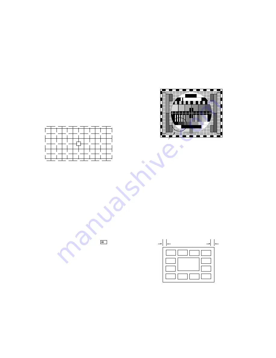
3. Pattern Position Adjustment
1) Change into pattern shift mode.
(Press numeric buttons “9” & “4”)
2) Make sure to overlap pattern and image.
(Use
M U T E
button)
3) Accord the center of image and pattern.
(Use
F
,
G
,
D
,
E
buttons)
4) Quit pattern shift mode. (Press “OK” button)
5) Save adjusted phase/pattern position adjustment
mode.(Press “9”, “2” & “OK” buttons)
4. Green Convergence Adjustment
1) Show the OSD on screen by pressing 2 button,then change the
OSD to green(G) adjustment mode with pressing TV/AV button.
2) Close the cover of red CRT and blue CRT so that green
display on screen only.
3) Adjust to coincide green pattern with screen jig pattern.
(Use
F
,
G
,
D
,
E
buttons)
Move cursor and adjust convergence in same way with item 3).
Here, do it in the same order from center listed in figure.
5. Red Convergence adjustment
1) Show the OSD on screen by pressing 2 button,then change the
OSD to red(R) adjustment mode with pressing TV/AV button.
2) If the need arises,close the cover of the blue lens.
3) Coincide the red screen with the green screen in same way
with that of green convergence adjustment.
6. Blue Convergence adjustment
1) Show the OSD on screen by pressing 2 button,then change the
OSD to blue(B) adjustment mode with pressing TV/AV button.
2) Coincide the blue screen with the green screen in same way
with that of red convergence adjustment.
7. Adjusted Data saving
1) Save the data after adjustment.
(Press “9”, “1” & “OK” button)
2) Quit convergence adjustment mode. (“ ” button)
O
White Balance Adjustment
1. Test Equipment
Brightness meter(CA110),Pattern Generator(Window Pattern)
2. Adjustment
1) This adjustment must be operated in a dark room or
equivalent.
2) Adjust after Cut-Off and Focus adjustment.
3) The brightness meter must be located in 20
¡ 5 c m
distance
from the center of the screen.
4) Receive WINDOW signal.
5) Set BRIGHT to H/Light adjustment mode in 4) and enter
SVC mode by pressing the “SVC” button. Adjust RG (R
Gain) and BG (B Gain) until color coordinate becomes
X=0.280 and Y=0.300 (Deviation :
!
0.01).
6) Set BRIGHT to L/Light adjustment mode and adjust CR (R
Cut Off) and CB (B Cut Off) until color coordinate becomes
X=0.282 and Y=0.286 (Deviation :
!
0.01).
7) Repeat adjusting until the color coordinate of H/Light and
L/Light is satisfied.
8) Save the data after adjustment.
(Press “OK” button)
9) Quit adjustment mode. (“ TV/AV ” button)
O
SUB-BRIGHT Adjustment
1) Tune the TV set to receive a EU 05 CH.
2) Enter
SVC mode by pressing the “SVC” button. Adjust S-
BRI data until 100% and 80% GRAY PATTERN is
classified.
(Use
F
,
G
,
D
,
E
,
ENTER
buttons)
O
DVCO Adjustment
1) Tune the TV set to receive a EU 05 CH.
2) Enter the adjustment mode by pressing SVC button of
Remote Controller for adjustment,then select DVCO menu.
Operate auto adjustment with VOL
G
button.
If DVCO data is changed,auto adjustment has finished.
3) After finishing DVCO adjustment,save the data by pressing
OK button.
O
PIP POSITION Adjustment
1) After receiving a PAL signal,show the multi-picture scan
screen on screen with pressing WD2 9/4PIP button.
2) Check the left,right blank on SCAN screen.(May be
20
±5mm)
3) If the left,right blank isn’t 20
±5mm and symmetry,enter the
adjustment mode by pressing SVC button of Remote
Controller for adjustment and select service adjustment
mode 5 by pressing YELLOW button.
4) Adjust M-HOR and M-VER to symmetry of left,right blank in
service adjustment mode 5.
5) When finishing adjustment,save the data by pressing OK
button.
- 14 -
8
6
5
4
5
6
8
7
5
3
2
3
5
7
6
4
2
1
2
4
6
7
5
3
2
3
5
7
8
6
5
4
5
6
8
100%,80% GRAY PATTERN
M
Left Blank
Right Blank
Summary of Contents for PE-43A82T
Page 30: ... 30 PRINTED CIRCUIT BOARD SIGNAL ...
Page 32: ... 32 MAIN2 DEF ...
Page 34: ... 34 SMPS NARROW SMPS WIDE ...
Page 35: ... 35 CPT CONV OUT ...
Page 36: ... 36 POWER S W SIDE AV CONTROL PRE AMP ...
Page 37: ... 37 VM TOP VM BOTTOM ...
Page 38: ... 38 CONVERGENCE TOP CONVERGENCE BOTTOM ...
Page 39: ... 39 MICOM TOP MICOM BOTTOM ...
Page 40: ... 40 100HZ TOP 100HZ BOTTOM ...
Page 41: ...AV TOP 41 AV BOTTOM ...
Page 43: ...MEMO 43 ...
Page 67: ......
Page 68: ... WIDE ...
Page 69: ......
Page 70: ......
Page 71: ......
Page 72: ......
Page 73: ...SVC SHEET 3854V A0094A S1 SVC SHEET 3854V A0094A S2 SVC SHEET 3854V A0094A S3 SVC SHE ...


