LG Multiplex 72 Service Manual Download Page 8

3-4

2) Adjustment

¤

Converge the RED vertical line and BLUE vertical line

the same line by changing the angle between the 2 tab
of the 4pole magnet.

¤Ł

Converge the RED horizontal line and BLUE horizontal

line in the same line by turning the table of the 4 pole
magnet. This time, go not change the angle between
the 2 tabs.

¤Ø

Converge the R, G, B vertical line in the same line by
changing the angle between the 2 tabs of the 6 pole
magnet.

¤Œ

Converge the R, G, B horizontal line in the same line
by turning the 2 tabs of the 6 pole magnet. This time,
do not change the angle between the 2 tabs.

4.4. Screen Voltage adjustment

1) Receive the PAL or SECAM(NTSC) signal into RF mode

regardless of channel.

2) If you press the ADJ button in LINE SVC mode(IN-START

button), the LINE SVC mode changes to screen
adjustment mode.

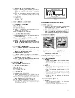
3) Turn the Screen Volume of FBT to changes luminance of

White signal center as shown below.

4) Press the EXIT button to exit SVC mode.

4.5 White Balance adjustment

4.5.1 Necessary Instrument 

1) Auto White Balance Meter
2) Color Analyzer (CA-100)
3) Factory Remote control

* Prior to this adjustment, the Screen Voltage Adjustment must

be finished.

4.5.2 Adjustment

1) Make the picture luminance 35Ft-L by changing the

“CONTRAST” and “BRIGHTNESS”.

2) Enter the white balance adjust mode with a factory remote

control.

3) Adjust HIGH Light status of WDR R, WDR B.
4) Make the picture luminance 4.5Ft-L by changing the

‘contrast’ and ‘brightness’.

5) Adjust LOW Light status of CUT R CUT B at CUT B.
6) Repeat 1) ~ 5) until both low and high light have same

color temperature.

* Note : When adjusting White balance automatically, connect
the adjustment JIG in SVC mode. (When pressing IN-START,
MUTE button on remote control for adjustment orderly, it
changes to SVC mode and screen displays SVC.)

* WHITE BALANCE INITIAL VALUE

CR,CG,CB => 80
WR,WG,WB => 800

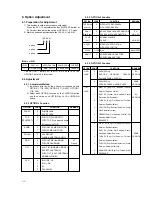
4.6. Deflection data adjustment

4.6.1. Preparation

1) At adjustment mode (IN-START button on remote control

of adjustment), changed to LINE SVC 2 mode to adjust
the deflection.

2) Press Channel UP/DOWN button for desirous function

adjustment.

3) Press Volume UP/DOWN button to adjust the data.
4) Tune the TV set to receive a Digital pattern.(PAL :

EU05CH, NTSC:13CH)

4.6.2. Deflection setting data adjustment

* Note : First, adjust deflection at N50Hz, W50Hz, Z50Hz of

PAL signal.
Then adjust deflection at N60Hz, W60Hz, Z60Hz of
NTSC signal.
In case of NTSC only model, adjust deflection at
N60Hz, W60Hz, Z60Hz of NTSC signal

¤

When adjusting a deflection, adjust N50Hz of PAL

signal first and adjust a deflection at W50Hz,
Z50Hz,N50Hz, W60Hz, Z60Hz of PAL signal.

¤Ł

Adust a deflection as shown below

PAL 4:3 -> PAL 16:9 -> PAL ZOOM -> NTSC 16:9 ->
NTSC ZOOM

¤Ø

After finishing deflection adjustment, press the ENTER

button to enter or exit in SVC mode.

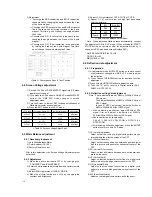
1) VA (Vertical Amplitude)

Adjust so that the circle of a digital circle pattern may be
located within the effective screen of the CPT.

2) VL (Vertical Linearity)

Adjust so that the boundary line between upper and lower
half is in accord with geometric horizontal center of the
CPT

3) SC (Vertical S-Correction)

Adjust so that all distance between each horizontal lines
are to be the same.

4) VS (Vertical Shift)

Adjust so that the horizontal center line of a digital circle
pattern is in accord with geometric center of the CPT.

5) HS (Horizontal Shift)

Adjust so that the vertical center line of a digital circle
pattern is in accord with geometric vertical center of the
CPT.

6) EW (East-West Width)

Adjust so that a digital circle pattern looks like exact.

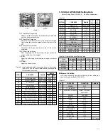
<Table 1> Convergence Spec. & Test Position

CPT & INCH

29”FLAT

21”FLAT

29”FLAT

21”FLAT

Luminance(Manual Adj.)

1 FL

12 

1 FL

1 FL

12 

1 FL

Luminance(Auto Adj.)

27 Cd

42 Cd

27 Cd

42 Cd

Description

KZ Model

KZ Model

KF Model

KF Model

<Table 2> Screen Voltage Adjust Spec.

X

Y

Temp.

EU

288

295

9000

Non-EU

268

273

13000

<Table 3> white Balance Adjust Spec.

Summary of Contents for Multiplex 72

Page 1: ... TV Triple Combi TV SERVICE MANUAL CAUTION BEFORE SERVICING THE CHASSIS READ THE SAFETY PRECAUTIONS IN THIS MANUAL CHASSIS MV 033A MODEL Multiplex 72 website http biz LGservice com e mail http www LGEservice com techsup html SERVICE MANUAL MODEL Multiplex 72 LG Electronics inc ...

Page 2: ...72 CONTENT SAFETY INSTRUCTIONS 1 2 SERVICING PRECAUTIONS 1 4 SPECIFICATION 1 5 DESCRIPTION OF CONTROLS 1 8 SECTION 1 SUMMARY ON OFF STOP PLAY OPEN CLOSE STOP EJECT PLAY REC ITR DVD TRK COPY VCR REC PM TV Triple Combi TV SERVICE MANUAL ...

Page 3: ...er details see the VCR Operation section 4 DVD BUTTONS controls a LG DVD player For further details see the DVD Operation section 5 RESET When Communicator does not work reset the Communicator by pressing the reset point with sharp one 6 POWER switches the set on from standby or off to standby 7 NUMBER BUTTONS switches the set on from standby or directly select a number 8 MENU selects a menu 9 D E...

Page 4: ...enera tor To charge the communicator do the followings 1 In first use 20 rotation of the handle in the arrow direction as picture below waiting for one minute 20 rotation again waiting for one minute again 20 rotation again beginning to use 2 In usual use 20 or 25 rotation resuming to use Note Do not rotate the handle too rapidly for the protection of the communicator TVCR DVD RESET EJECT PSM SSM ...

Page 5: ...ARTMENT Inserts a video cassette tape here 8 STOP EJECT stops the tape during playback or recording or ejects the tape 9 D D E E Programme Up Down selects a programme or a menu item switches the set on from standby F F G G Volume Down Up adjusts the volume adjusts menu settings 10 REC ITR starts a manual recording or instant timer recording 11 POWER r r I switches the set on from standby or off to...

Page 6: ...level adjustment 3 OSCILLOSCOPE 4 10 1 PROBE 2 PIECES 5 RMS METER for Audio level adjustment 3 2 2 CTL ADJUSTMENT THIS ADJUSTMENT MUST BE DONE WHEN THE UNCONTROLLED DECK IS WAREHOUSED 1 Connect the OSCILLOSCOPE to J101 CTL 2 After playing the CTL control tape make sure the CTL waveform range is From 1 5 1 to 2 5 1 If it is out of range adjust CTL waveform to the following procedures If is over 2 5...

Page 7: ...61 on the main PCB and trigger in setting the VOL DIV to 1V range 3 Connect the oscilloscope CH 2 to video out C571 on the main PCB and set the VOL DIV to 500mV range 4 Set the TIME DIV of oscilloscope to 50us range 5 If press P CHECK of SVC Remote control A PG is appeared in the display and PG adjustment signal become 412uS 100uSec 4 ASSEMBLY LINE ADJUSTMENT 4 1 DVCO adjustment 1 This is for adju...

Page 8: ...WR WG WB 800 4 6 Deflection data adjustment 4 6 1 Preparation 1 At adjustment mode IN START button on remote control of adjustment changed to LINE SVC 2 mode to adjust the deflection 2 Press Channel UP DOWN button for desirous function adjustment 3 Press Volume UP DOWN button to adjust the data 4 Tune the TV set to receive a Digital pattern PAL EU05CH NTSC 13CH 4 6 2 Deflection setting data adjust...

Page 9: ...Amplitude Vertical Linearity S Correction Vertical Shift Horizontal Shift East West Width East West Trapezium East West Parabola East West Symmetric East West corner Bow Correction Quadratic Angle Correction Linear 0050 00CF 0025 00BF 0000 009F 0600 0900 0000 003F 0400 0EFF 0700 08FF 06E0 0840 06A0 0AFF 0790 08E0 256 255 256 255 00A1 00FB 00D0 0738 0017 0B04 07F8 07B0 0840 0825 0000 0000 160 0 32 ...

Page 10: ...AUSSING WITH DEGAUSSING W O TILT NORMAL MODEL EXCEPT AUSTRALIA WITH TILT FLAT AUSTRALIA NORMAL MODEL B G I DK L L B G I DK M PAL N M M REMARK 21 Option OPTION TSS Turbo search DUAL Dual Save V CUR Vol HOTEL M VOL MONO CODE 0 1 0 1 0 1 0 1 1 100 0 1 FUNCTION WITHOUT TURBO SEARCH WITH TURBO SEARCH NO SAVE DUAL SOUND CONDITION SAVE DUAL SOUND CONDITION NORMAL VOLUME CURVE WITHOUT HOTEL OPTION WITH HO...

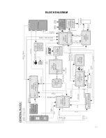
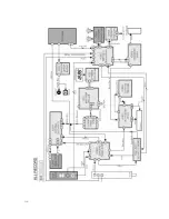
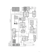
Page 11: ...3 7 BLOCK DIAGRAM ...

Page 12: ...3 8 ...

Page 13: ...3 9 ...

Page 14: ...mp Flicker Check Replace Deck Assy NO Check Replace Mode Switch P02 No Play Of VCR Open Close Control Check Replace The DVD Loader NG OK No Play Of DVD Check the voltage of P751A pin1 3 6 3 3V 12V 5 3V Bad Disc No Disc On the Menu Check the Disc Condition Check the Regional Code On Disc Check The VCR SMPS Board NO OK 3 10 ...

Page 15: ...701 Relay Check the power CTL of IC01 Pin27 Check Waveform of P821 Pin9 H out Check Q401 collector waveform Check T402 voltage Check replace IC501 Check replace Q401 Check the in out of IC801 Check the D801 Check replace RL701 OK NO OK OK Yes No No No No OK Open Go to No Power Block No ...

Page 16: ...em in MENU Check the waveform of PIN 4 12 IC851 Check the waveform of PIN 27 28 IC601 Check the Freq of X600 X tal CheckVcc replace IC851 OK NO NO OK Check replace P500 Connector OK Check replace Tuner Audio Line OK Check replace VCC IIC line NO ...

Page 17: ...heck the Waveform of IC501 Pin42 43 44 Check FR901 FR401 Check FBT T402 Check the Heater Volt 6 0V 6 4V Check The Main Power Board OK OK Not OK Check Replace IC501 Not OK Check VCC of IC501 Pin 3 15 25 45 54 3 3V or 5V OK Not OK ...

Page 18: ...Flicker Check Replace DeckAssy NO Check Replace Mode Switch P02 No Play Of VCR Open Close Control Check Replace The DVD Loader NG OK No Play Of DVD Check the voltage of P751A pin1 3 6 3 3V 12V 5 3V Bad Disc No Disc On the Menu Check the Disc Condition Check the Regional Code On Disc Check The VCR SMPS Board NO OK ...

Page 19: ...P NO 3854VA0122A S1 1 2 2004 2 26 ...

Page 20: ...P NO 3854VA0122A S1 2 2 2004 2 26 ...

Reviews: