LG MU-60PZ12V Owner'S Manual Download Page 6

6

SAFETY INSTRUCTIONS

The openings should never be blocked by
placing the product on a bed, sofa, rug, or
other similar surface. This product should
not be placed in a built-in installation such
as a bookcase or rack unless proper ventila-
tion is provided or the manufacturer’s
instructions have been adhered to.

11. Power Sources

This product should be operated only from
the type of power source indicated on the
marking label. If you are not sure of the type
of power supply to your home, consult your
product dealer or local power company. For
products intended to operate from battery
power, or other sources, refer to the operat-
ing instructions.

12. Power-Cord Polarization

This product is equipped with a polarized
alternating-current line plug (a plug having
one blade wider than the other). This plug
will fit into the power outlet only one way.
This is a safety feature. If you are unable to
insert the plug fully into the outlet, try
reversing the plug. If the plug should still fail
to fit, contact your electrician to replace your
obsolete outlet. Do not defeat the safety
purpose of the polarized plug.

13. Power-Cord Protection

Power-supply cords should be routed so
that they are not likely to be walked on or
pinched by items placed upon or against
them, paying particular attention to cords at
plugs, convenience receptacles, and the
point where they exit from the product.

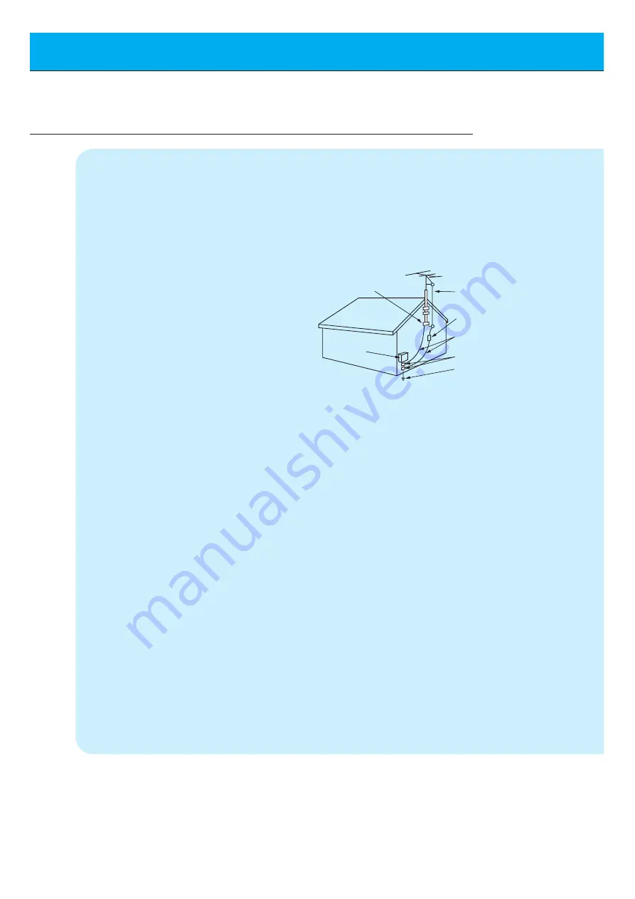
14. Outdoor Antenna Grounding

If an outside antenna or cable system is
connected to the product, be sure the
antenna or cable system is grounded so as
to provide some protection against voltage
surges and built-up static charges. Article
810 of the National Electrical Code (U.S.A.),
ANSI/ NFPA 70 provides information with
regard to proper grounding of the mast and

supporting structure, grounding of the lead-
in wire to an antenna discharge unit, size of
grounding conductors, location of antenna-
discharge unit, connection to grounding
electrodes, and requirements for the
grounding electrode.

15. Lightning

For added protection for this product
(receiver) during a lightning storm, or when
it is left unattended and unused for long
periods of time, unplug it from the wall outlet
and disconnect the antenna or cable sys-
tem. This will prevent damage to the product
due to lightning and power-line surges.

16. Power Lines

An outside antenna system should not be
located in the vicinity of overhead power
lines or other electric light or power circuits,
or where it can fall into such power lines or
circuits. When installing an outside antenna
system, extreme care should be taken to
keep from touching such power lines or cir-
cuits as contact with them might be fatal.

17. Overloading

Do not overload wall outlets and extension
cords as this can result in a risk of fire or
electric shock.

18. Object and Liquid Entry

Never push objects of any kind into this

(Continued from previous page)

Antenna Lead in Wire

Antenna Discharge Unit
(NEC Section 810-20)

Grounding Conductor
(NEC Section 810-21)

Ground Clamps

Power Service Grounding
Electrode System (NEC
Art 250, Part H)

Ground Clamp

Electric Service

Equipment

Example of Grounding According to National
Electrical Code Instructions

NEC - National Electrical Code

Summary of Contents for MU-60PZ12V

Page 1: ...ore operating the Monitor Retain it for future reference Record model number and serial number of the Monitor See the label attached on the back of the Monitor and quote this information to your dealer when you require service Model number Serial number MU 60PZ12V MU 60PZ12VA MU 60PZ12VB MU 60PZ12VK MU 60PZ12VS OWNER S MANUAL ...

Page 2: ...ns that it is not change able nor refundable FCC NOTICE MU 60PZ12V VA VB VK VS A Class B digital device This equipment has been tested and found to comply with the limits for a Class B digital device pursuant to Part 15 of the FCC Rules These limits are designed to provide reasonable protection against harmful interference in a residential installation This equipment generates uses and can radiate...

Page 3: ...ture function 29 Using the remote control 31 Basic Features Setup and Operation Turning on the Monitor 32 OSD Display Rotation 33 Checking features 34 Sleep Timer Setting Sleep Timer Monitor turn off time 35 Picture Sound Auto picture control 36 Adjusting picture appearance 37 DRP Digital Reality Picture 38 Adjusting Sound Bass Treble Balance 39 Auto Sound Control 40 AVL Auto volume leveler 41 Spe...

Page 4: ...ct s enclosure that may be of sufficient magnitude to consti tute a risk of electric shock to persons The exclamation point within an equilateral triangle is intended to alert the user to the presence of important operating and maintenance servicing instructions in the literature accompanying the appliance WARNING TO PREVENT FIRE OR SHOCK HAZARDS DO NOT EXPOSE THIS PRODUCT TO RAIN OR MOISTURE CAUT...

Page 5: ...ed to 5 Cleaning Unplug this product from the wall outlet before cleaning Do not use liquid cleaners or aerosol cleaners Use a damp cloth for cleaning 6 Water and Moisture Do not use this product near water for example near a bath tub wash bowl kitchen sink or laundry tub in a wet base ment or near a swimming pool 7 Accessories Carts and Stands Do not place this product on a slippery or tilted sur...

Page 6: ... antenna or cable system is grounded so as to provide some protection against voltage surges and built up static charges Article 810 of the National Electrical Code U S A ANSI NFPA 70 provides information with regard to proper grounding of the mast and supporting structure grounding of the lead in wire to an antenna discharge unit size of grounding conductors location of antenna discharge unit con...

Page 7: ...uctions as an improper adjustment of other controls may result in damage and will often require extensive work by a qualified technician to restore the product to its normal operation e If the product has been dropped or the cabinet has been damaged f If the product exhibits a distinct change in performance 21 Replacement Parts When replacement parts are required be sure the service technician has...

Page 8: ...VOLUME INPUT SELECT VOLUME Front Panel Controls Main power button INPUT SELECT button Power standby indicator Illuminates red in standby mode Illuminates green when the Monitor is turned on Sub power button VOLUME F F G G buttons Remote control sensor ...

Page 9: ...TROL LOCK L AUDIO VGA SVGA XGA SXGA RGB DTV INPUT 480p 720p 1080i VIDEO Y PB PR DVD DTV INPUT 480i 480p 720p 1080i RS 232C ON OFF ON OFF Back Panel A V INPUT COMPONENT 480i 480p 720p 1080i DVD DTV INPUT jacks EXTERNAL SPEAKER 8 ohm output CONTROL LOCK REMOTE CONTROL When CONTROL LOCK is set ON wired remote con trol mode is operated The wired remote control can be operated even if no batteries are ...

Page 10: ...nitor POWER SLEEP INPUT SELECT APC DASP ARC STILL PIP PIP INPUT MENU MUTE OK VOL POWER STOP PLAY FF REC REW P STILL VOL POSITION TWIN PICTURE POWER SLEEP Refer to p 35 APC Refer to p 36 ARC Refer to p 46 PIP Refer to p 26 PIP INPUT Refer to p 27 30 MENU OK VCR BUTTONS controls a LG video cassette recorder VOLUME F F G G ...

Page 11: ... PIP PIP INPUT MENU MUTE OK VOL POWER STOP PLAY FF REC REW P STILL VOL POSITION TWIN PICTURE Remote control Owner s Manual Alkaline batteries video pc button on the remote control Each press of this button changes the mode as shown below S VIDEO COMPONENT VIDEO RGB INPUT SELECT DASP Refer to p 40 STILL Refer to p 42 POSITION Refer to p 27 D D E E selects a menu item MUTE switches the sound on or o...

Page 12: ...This plasma display is designed to be mounted horizontally or vertically Wall Mount Installation horizontally The monitor can be installed on the wall as shown above For further information refer to the optional Wall mounting bracket Installation and Setup Guide Speakers are optional and shown for illustration only Tip Install this monitor only in a location where adequate ventilation is available...

Page 13: ...ertically The monitor can be installed vertically on the wall as shown above For further information refer to the optional Wall mounting bracket Installation and Setup Guide Speakers are optional and shown for illustration only Tip When installing the monitor you have to change the OSD display mode to protect it from overheating Refer to P 33 ...

Page 14: ...ght red If you have a mono VCR connect the audio cable from the VCR to the AUDIO L MONO input of the Plasma Monitor If you connect an S VIDEO VCR to the S VIDEO input the picture quality is improved compared to connecting a regular VCR to the Video input Avoid having a fixed image remain on the screen for a long period of time A frozen still picture from a VCR or if a CH label is displayed display...

Page 15: ... MONO R L AV INPUT S VIDEO COMPONENT 480i 480p 720p 1080i DVD DTV INPUT RGB PC INPUT R AUDIO INPUT EXTERNAL SPEAKER 8Ω R L AC INPUT L AUDIO VGA SVGA XGA SXGA RGB DTV INPUT 480p 720p 1080i VIDEO Y PB PR RS 232C CONTROL LOCK REMOTE CONTROL REMOTE CONTROL CONTROL LOCK ON OFF ON OFF Back panel of the Monitor To watch VCR Press INPUT SELECT button on the remote control and select VIDEO When connecting ...

Page 16: ...80p 720p 1080i DVD DTV INPUT AUDIO MONO R L AV INPUT S VIDEO COMPONENT 480i 480p 720p 1080i DVD DTV INPUT RGB PC INPUT R AUDIO INPUT EXTERNAL SPEAKER 8Ω R L AC INPUT L AUDIO VGA SVGA XGA SXGA RGB DTV INPUT 480p 720p 1080i VIDEO Y PB PR RS 232C RS 232C CONTROL LOCK REMOTE CONTROL REMOTE CONTROL CONTROL LOCK ON OFF To watch cable TV Press INPUT SELECT button on the remote control and select VIDEO so...

Page 17: ... L AC INPUT L AUDIO VGA SVGA XGA SXGA RGB DTV INPUT 480p 720p 1080i VIDEO Y PB PR Camcorder Video game set DDR RS 232C RS 232C CONTROL LOCK REMOTE CONTROL REMOTE CONTROL CONTROL LOCK ON OFF ON OFF To watch external AV source Press INPUT SELECT button on the remote control of the monitor to select VIDEO 1 Operate the corresponding external equip ment See external equipment operating guide 2 Externa...

Page 18: ...L Y PB R P DTV OUTPUT AUDIO MONO R L VIDEO Y PB R P AV INPUT AUDIO R L R L EXTERNAL SPEAKER 8Ω AC INPUT AUDIO INPUT S VIDEO COMPONENT 480i 480p 720p 1080i RGB PC INPUT VGA SVGA XGA SXGA RGB DTV INPUT 480p 720p 1080i DVD DTV INPUT AUDIO MONO R L AV INPUT S VIDEO COMPONENT 480i 480p 720p 1080i DVD DTV INPUT RGB PC INPUT R AUDIO INPUT EXTERNAL SPEAKER 8Ω R L AC INPUT L AUDIO VGA SVGA XGA SXGA RGB DTV...

Page 19: ...i DVD DTV INPUT AUDIO MONO R L AV INPUT S VIDEO COMPONENT 480i 480p 720p 1080i DVD DTV INPUT RGB PC INPUT R AUDIO INPUT EXTERNAL SPEAKER 8Ω R L AC INPUT L AUDIO VGA SVGA XGA SXGA RGB DTV INPUT 480p 720p 1080i VIDEO Y PB PR RS 232C RS 232C CONTROL LOCK REMOTE CONTROL REMOTE CONTROL CONTROL LOCK ON OFF ON OFF Turn on the digital SET TOP BOX Refer to the owner s manual for the digital SET TOP BOX Pre...

Page 20: ...f the Monitor Audio cables are not supplied with the Monitor To set up the Monitor to operate within a PC win dows environment select Normal Standard or Default monitor The Monitor can not be used for Plug and Play functionality If your PC computer is equipped with a sound card adjust the sound output on the PC It is recommended that the resolution output of the PC should be set to 1280 x 720 to g...

Page 21: ...0 03 53 011 100 04 64 062 120 00 35 156 56 25 37 879 60 31 48 077 72 18 46 875 832x624 1024x768 1280x720 1152x864 1152x870 1280x960 1280x1024 75 00 53 674 85 06 56 000 90 00 64 016 100 00 49 725 74 55 48 363 60 00 56 476 70 06 60 023 75 02 68 677 84 99 54 348 60 05 52 400 69 98 63 995 70 01 67 500 75 00 77 487 85 05 68 681 75 06 60 000 60 00 75 000 75 00 63 981 60 02 79 976 75 02 Resolution Horizo...

Page 22: ...elect a feature you want to use Press the OK button to exit menus Press the D E button to select a menu Each press will cycle through the different menus as shown below APC G DRP G CONTRAST 85 G BRIGHTNESS 50 G COLOR 50 G TINT 0 G SHARPNESS 50 G MOVE GNEXT AEXIT D E DASP G AVL G TREBLE 50 G BASS 50 G BALANCE 0 G MOVE GNEXT AEXIT D E OSD ROTATE G ARC G SCREEN G TRANSPARENCY G PIP DW G SET ID G COLO...

Page 23: ...ss the D E button to select AUTO CONFIG and then press the G button When AUTO CONFIG has finished OK will be shown on screen If the position of the image is incorrect try Auto adjustment again LANGUAGE G CAPTION G AUTO OFF G SCREEN G RGB OUTPUT G AUTO CONFIG G V POSITION G H POSITION G PHASE G RESET G G TO SET AUTO CONFIG OSD ROTATE G ARC G SCREEN G TRANSPARENCY G PIP DW G SET ID G COLOR TEMP G G ...

Page 24: ...t change even though you have adjusted the horizontal or vertical position with this function Press the F G buttons to adjust until you get desired horizontal or vertical position and then press the OK button to remove menus Press the MENU button and then press the D E button to select menu Press the G button LANGUAGE G CAPTION G AUTO OFF G SCREEN G RGB OUTPUT G AUTO CONFIG G V POSITION G H POSITI...

Page 25: ...ilable Initializing Reset to factory value To initialize the adjusted value select RESET with the D E button and then press the G button Press the D E button to select PHASE and then press the G button The adjustment range of PHASE is 0 63 Press the F G button to adjust phase and then press the OK button LANGUAGE G CAPTION G AUTO OFF G SCREEN G RGB OUTPUT G AUTO CONFIG G V POSITION G H POSITION G ...

Page 26: ...n picture you can watch video cable TV or DVD for sub picture Color of main picture may be different from PIP s in PIP Twin picture mode If input source for main picture is changed while in PIP Twin picture mode sub picture will disappear When watching PIP Twin picture SCREEN option is not available in Special menu With PIP active not all picture formats can be used for the main sub picture Watchi...

Page 27: ... button in PIP mode Each time you press PIP INPUT button you toggle VIDEO S VIDEO and COMPONENT COMPONENT source only works in 480i mode VIDEO S VIDEO COMPONENT PIP INPUT F VIDEO G Moving the Sub inset picture Press the POSITION button in PIP mode Each press of the POSITION button will change the position of the sub picture on the screen as shown below PIP INPUT POSITION ...

Page 28: ...EEN G RGB OUTPUT G DW G PIP G INPUT G SOUND SELECT G POSITION G SOUND M SOUND S OSD ROTATE G ARC G SCREEN G TRANSPARENCY G PIP DW G SET ID G COLOR TEMP G G TO SET PIP DW To select main or sub inset sound This function only works with the following resolutions 640x480 800x600 1024x768 only in Vertical frequency 60 Hz To use this function connect PC DTV video output to RGB PC INPUT RGB DTV INPUT and...

Page 29: ...640x480 only in Vertical frequency 60 Hz With TWIN PICTURE active not all picture formats can be used for the main sub picture Press the TWIN PICTURE button Each time you press TWIN PICTURE or F G buttons you can select ON or OFF ON OFF DW F OFF G DW F ON G Sub picture Main picture To avoid a permanent image being burned into the screen the sub picture will move every 2 hours Center Upside Downsid...

Page 30: ... the Twin picture Press the PIP INPUT button in TWIN PICTURE mode Each time you press PIP INPUT button you toggle VIDEO S VIDEO and COMPONENT COMPONENT source only works in 480i input signal PIP INPUT F VIDEO G VIDEO S VIDEO COMPONENT PIP INPUT ...

Reviews: