3. H/W Circuit Description
- 16 -
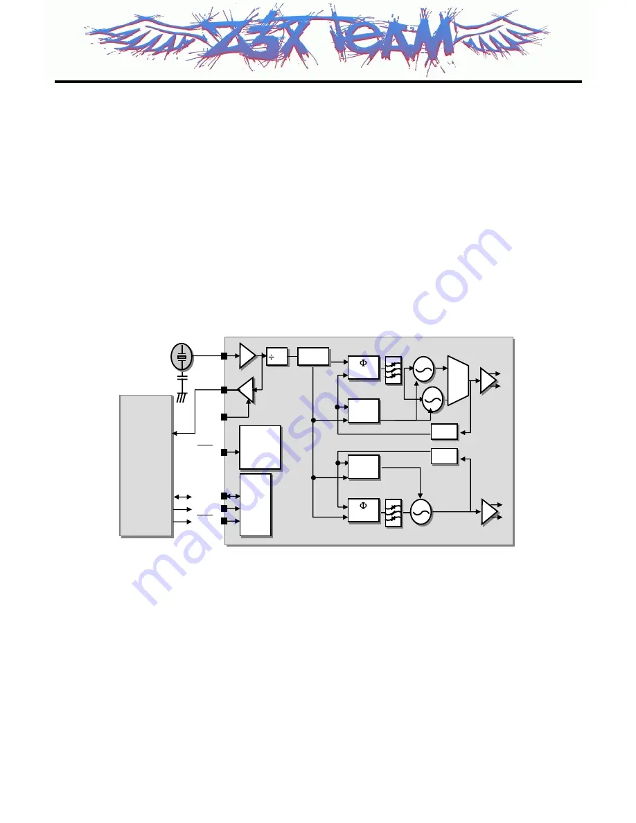
3.2.2. Synthesizer
The Aero II transceiver integrates two complete PLLs including VCOs, varactors, resonators, loop
filters, reference and VCO dividers, and phase detectors. The RF PLL uses two multiplexed VCOs.
The RF1 VCO is used for receive mode, and the RF2 VCO is used for transmit mode. The IF PLL is
used only during transmit mode. All VCO tuning inductors are also integrated. The IF and RF output
frequencies are set by programming the N-Divider registers, NRF1, NRF2 and NIF. Programming the
N-Divider register for either RF1 or RF2 automatically selects the proper VCO.
Transmit modes should always use f
∅
= 200kHz. The IF and RF output frequencies are set by
programmi ng the N-Divider registers and also programmed via 3-wire interface with external system
controler.
Serial
I/O
Serial
I/O
Baseband
(TI)
U100
IOTA
+
U101
Calypso-
Baseband
(TI)
U100
IOTA
+
U101
Calypso-
U501/Si4210
RF1
RF2
PDIB
26MHz
X500
VC-TCXO
SCLK
SDIO
SEN
PDN
XTAL1
XOUT
XEN
Power
control
Power
control
Self
Tune
Self
Tune
1/N
1/N
1/N
1/N
DET
DET
Self
Tune
Self
Tune
DET
DET
To Rx/Tx
To Tx
RF PLL
IF PLL
PDRB
SDOSEL[4:0]
N
IF
[15:0]
N
RF1
[15:0]
N
RF2
[15:0]
1,2
1,2
65,130
65,130
Figure 2. Synthesizer Block
Z3X-BOX.COM
Summary of Contents for MG220
Page 1: ...Date May 2006 Issue 1 0 Service Manual MG220 Service Manual Model MG220 Z 3 X B O X C O M ...
Page 3: ... 2 Z 3 X B O X C O M ...
Page 5: ...Z 3 X B O X C O M ...
Page 32: ...3 H W Circuit Description 31 Figure 14 Power Supply Scheme Z 3 X B O X C O M ...
Page 46: ...4 TROUBLE SHOOTING 45 4 TROUBLE SHOOTING 4 1 Main Components Placement Z 3 X B O X C O M ...
Page 93: ...5 DOWNLOAD 92 5 2 3 Configuration Setting C GSMULTI Model MG220 dll Z 3 X B O X C O M ...
Page 94: ...5 DOWNLOAD 93 5 2 4 Press Start Button Z 3 X B O X C O M ...
Page 95: ...5 DOWNLOAD 94 5 2 5 After Start Button Which Stand by condition Z 3 X B O X C O M ...
Page 96: ...5 DOWNLOAD 95 5 2 6 SW downloading Condition MG220 Z 3 X B O X C O M ...
Page 97: ...5 DOWNLOAD 96 5 2 7 SW downloading END Condition Z 3 X B O X C O M ...
Page 99: ...6 SERVICE AND CALIBRATION 98 4 Click on CALIBRATION START button Z 3 X B O X C O M ...
Page 108: ... 107 8 pcb layout Z 3 X B O X C O M ...
Page 109: ... 108 8 pcb layout Z 3 X B O X C O M ...
Page 113: ... 112 Z 3 X B O X C O M ...
Page 129: ...Note Z 3 X B O X C O M ...
Page 130: ...Note Z 3 X B O X C O M ...