background image

80

APPENDIX

EXTERNAL CONTROL DEVICE SETUP

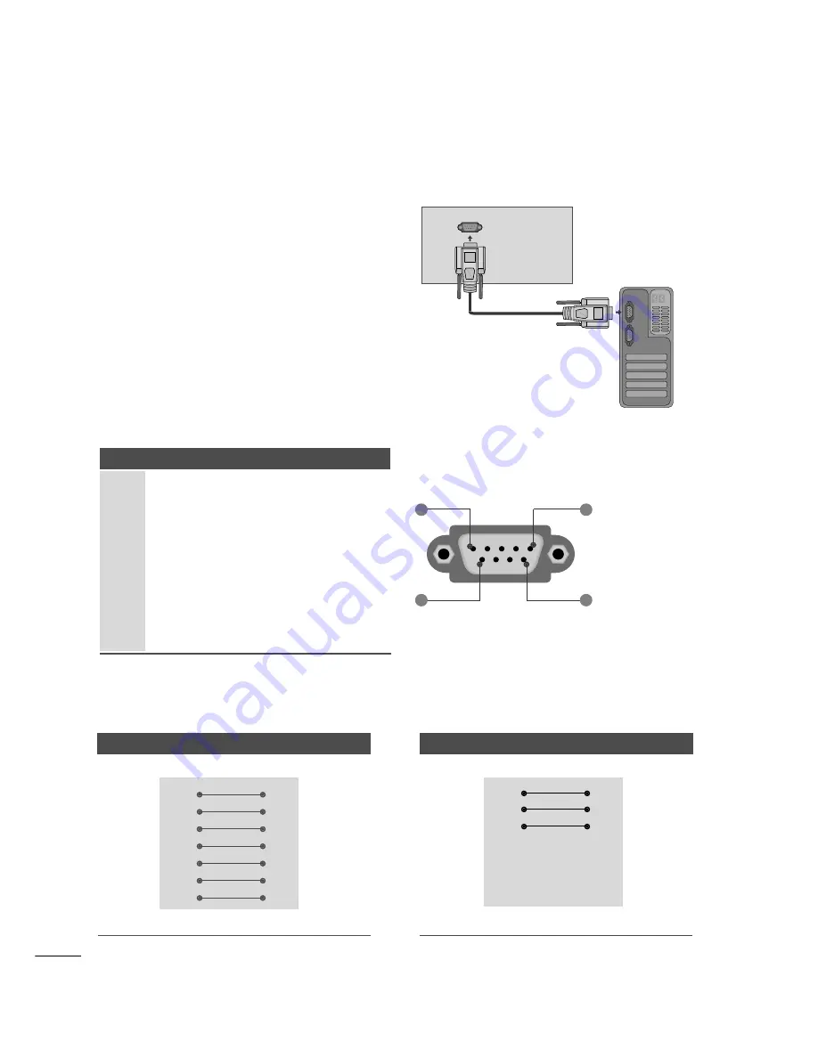
RS-232C Setup

Connect the RS-232C (serial port) input jack to an
external control device (such as a computer or an A/V
control system) to control the product’s functions
externally.

Connect the serial port of the control device to the
RS-232C jack on the product back panel.

Note: RS-232C on this unit is intended to be used
with third party RS-232C control hardware and soft-
ware. The instructions below are provided to help with
programming software or to test functionality using
telenet software. RS-232C connection cables are not
supplied with the product.

Type of Connector; D-Sub 9-Pin Male

No. 

Pin Name

No connection

2

RXD (Receive data)

3

TXD (Transmit data)

4

DTR (DTE side ready)

5

GND

6

DSR (DCE side ready)

7

RTS (Ready to send)

8

CTS (Clear to send)

9

No Connection

RS-232C IN

(CONTROL & SERVICE)

1

5

6

9

RS-232C Configurations

7-Wire Configuration (Serial female-female NULL modem cable)

PC

TV

RXD 

2

3

TXD

TXD

3

2

RXD

GND

5

5

GND

DTR

4

6

DSR

DSR

6

4

DTR

RTS

7

8

CTS

CTS

8

7

RTS

D-Sub 9

D-Sub 9

3-Wire Configurations(Not standard)

PC

TV

RXD 

2

3

TXD

TXD

3

2

RXD

GND

5

5

GND

DTR

4

6

DTR

DSR

6

4

DSR

RTS

7

7

RTS

CTS

8

8

CTS

D-Sub 9

D-Sub 9

Summary of Contents for M237WD-PM

Page 1: ...tions before using the product Keep the User s Guide CD in an accessible place for furture reference See the label attached on the product and give the information to your dealer when you ask for service OWNER S MANUAL M M2 23 37 7W WD D ...

Page 2: ...S This is a simplified representation of the front panel The image shown may be somewhat different from your set INPUT MENU VOL CH ENTER CHANNEL Buttons VOLUME Buttons MENU Button ENTER Button INPUT Button Power Button Headphone Output ...

Page 3: ...uts accept TV Video not PC Video They also accept TV Video from a DVI connection when using an adapter The HDMI inputs support video and audio When using an adapter for DVI they only accept video RGB DVI Audio Input This is the audio input for the RGB and DVI D video inputs Optical Digital Audio Out Use this to export audio to an external amplifer RGB INPUT PC Analog PC input Also known as VGA S V...

Page 4: ... 3 Carefully place the product screen side down on a cushioned surface that will protect product and screen from damage Insert the s st ta an nd d b ba as se e into the product Attach the monitor to the Stand Base by turning the screw to the right Turn the screw by using the screw handle Screw ...

Page 5: ...e set screen side down on a cushion or soft cloth Detach the monitor from the Stand Base by turning the screw to the left Turn the screw by using the screw handle 4 Pull the stand base 5 The image shown may be somewhat different from your monitor ...

Page 6: ... inches on each side and from the wall 4 inches 4 inches 4 inches 4 inches WALL MOUNT HORIZONTAL INSTALLATION For proper ventilation allow a clearance of 4 inches on each side and from the wall Follow the instructions included with the wall mount 4 inches 4 inches 4 inches 4 inches 4 inches ...

Page 7: ...nterface optional parts to the back of the set When you install the set using the wall mounting interface optional parts attach it carefully so it will not drop Be sure to use screws and a wall mount that meet VESA standards Using screws longer than those recommended might damage the product Using screws that do not meet VESA standards might either damage the product or result in it coming away fr...

Page 8: ... inserting the eye bolts loosen the bolts Insert the eye bolts or set brackets bolts and tighten them securely in the upper holes Secure the wall brackets with the bolts sold separately to the wall Match the height of the bracket that is mounted on the wall to the holes in the product Ensure the eye bolts or brackets are tightened securely Use a sturdy rope or cord sold separately to tie the produ...

Page 9: ...page of the Kensington company Kensington sells security systems for expensive electronic equipment such as note book PCs and LCD projectors NOTE The Kensington Security System is an optional accessory available at most electronics stores NOTES a If the product feels cold to the touch there may be a small flicker when it is turned on This is normal there is nothing wrong with product b Some minute...

Page 10: ...nnect to wall antenna socket Single family Dwellings Houses Connect to wall jack for outdoor antenna Outdoor Antenna VHF UHF Wall Antenna Socket RF Coaxial Wire 75 ohm ANTENNA CONNECTION Antenna UHF VHF In poor signal areas to get better picture quality install a signal amplifier to the antenna as shown above If signal needs to be split for two TVs use an antenna signal splitter for connection AC ...

Page 11: ...O sockets of the set Press the I IN NP PU UT T button to select Component 2 3 1 HD RECEIVER SETUP To prevent the equipment damage never plug in any power cords until you have finished connecting all equipment The image shown may be somewhat different from your set When connecting with a component cable Signal 480i 480p 576p 720p 1080i 1080p Component Yes Yes No Yes Yes HDMI No Yes Yes Yes Yes VIDE...

Page 12: ... Connect the audio output of the digital set top box to the A AU UD DI IO O I IN N R RG GB B D DV VI I jack on the set Turn on the digital set top box Refer to the owner s manual for the digital set top box 2 3 1 When connecting with a HDMI to DVI cable HDMI IN 1 2 1 DVI OUTPUT AUDIO R L AUDIO IN RGB DVI HDMI IN 1 2 1 2 NOTE G G HDMI Input does not support PC mode If it is connected PC the screen ...

Page 13: ... Y Y PB B Y Cb Pb PR R Y Cr Pr Connect the video output sockets Y PB PR of the DVD to the C CO OM MP PO ON NE EN NT T I IN N V VI ID DE EO O sockets Y PB PR of the set Connect the audio cable from the DVD to C CO OM MP PO ON NE EN NT T I IN N A AU UD DI IO O sockets of the set Press the I IN NP PU UT T button to select Component Press the P PL LA AY Y button on the DVD The DVD playback picture app...

Page 14: ...eed to connect a sperate audio cable G G If the DVD player does not support Auto HDMI you need to set the DVD output resolution appropriately NOTE HDMI IN 1 2 1 When connecting S Video Connect the S Video output of the DVD to the S Video in put on the set Connect the audio output of the DVD to the AUDIO in put on the set 1 2 VIDEO AUDIO MONO S VIDEO L R AV IN VIDEO S VIDEO L R 1 2 ...

Page 15: ...T SWITCH ANT IN R S VIDEO VIDEO ANT OUT L ANTENNA CABLE IN AV 1 AV 2 Wall Jack Antenna 1 2 When connecting with an antenna Connect the RF out socket of the VCR to the antenna socket of the set Connect the antenna cable to the RF aerial in socket of the VCR Store the VCR channel on a desired channel number using the Manual channel tuning section Select the Channel number where the VCR channel is st...

Page 16: ...cable Connect the S Video socket of the VCR to the S VIDEO socket of the set Connect the audio cable from the S VIDEO of the VCR to the AUDIO sockets of the set Press the INPUT button to select AV Press the PLAY button on the VCR The VCR playback picture appears on the screen 2 3 4 1 NOTE G G If you have a mono VCR connect the audio cable from the VCR to the AUDIO L MONO jack of the set VIDEO AUDI...

Page 17: ...o the PC input socket of the set Connect the audio cable from the PC to the A AU UD DI IO O I IN N R RG GB B D DV VI I sockets of the set Press the INPUT button to select RGB Switch on the PC and the PC screen appears on the set The set can be operated as a PC monitor 2 3 1 RGB OUTPUT AUDIO AUDIO IN RGB DVI RGB IN PC 1 2 NOTE G G User must use shielded signal interface cables D sub 15 pin cable DV...

Page 18: ... your LCD moni tor If used with other resolutions some scaled or processed pictures may appear on the screen The set has been preadjusted to the mode 1920x1080 60Hz G G Some dot defects may appear on the screen like Red Green or Blue spots However this will have no impact or effect on the monitor performance G G Do not press the LCD screen with your finger for a long time as this may produce some ...

Page 19: ...18 EXTERNAL EQUIPMENT SETUP Tie cables together with a cable tie as shown in the illustration Cable tie BACK COVER FOR WIRE ARRANGEMENT ...

Page 20: ...1280x720 60p 1280x720 50p Horizontal Frequency kHz Vertical Frequency Hz 1920x1080 60i 1920x1080 50i 1920x1080 24p 1920x1080 30p 1920x1080 50p 1920x1080 60p Resolution 640x480 800x600 720x400 1024x768 Horizontal Frequency kHz Vertical Frequency Hz 70 60 75 60 75 60 75 75 60 75 60 60 60 60 31 468 31 469 37 500 37 879 46 875 48 363 60 123 67 500 63 981 79 976 64 674 65 290 75 000 66 587 1280x1024 1 ...

Page 21: ... Select SCREEN RGB PC 3 ENTER Select Reset 5 ENTER Run Reset Contrast 90 Brightness 50 Sharpness 70 Colour 50 Tint 0 Advanced Control Reset PICTURE Move Enter D Screen RGB PC Initialize Settings Auto Config SCREEN Move Prev BACK Resolution Position Size Phase Reset G ENTER 4 ENTER Select Yes Press the MENU button to close the menu window Press the RETURN button to move to the previous menu screen ...

Page 22: ...n Size Phase 1 Select PICTURE 2 Select SCREEN RGB PC 3 Select Position Size or Phase 4 Make appropriate adjustments Auto Config SCREEN Move Resolution Position G Size Phase Reset G F D E MENU ENTER ENTER Press the MENU button to close the menu window Press the RETURN button to move to the previous menu screen Prev BACK Contrast 90 Brightness 50 Sharpness 70 Colour 50 Tint 0 Advanced Control Reset ...

Page 23: ...lect SCREEN RGB PC 3 Select Resolution 4 Select the desired resolution MENU ENTER ENTER Press the MENU button to close the menu window Press the RETURN button to move to the previous menu screen 1400 x 1050 1680 x 1050 Auto Config SCREEN Move Resolution G Position Size Phase Reset Prev BACK Contrast 90 Brightness 50 Sharpness 70 Colour 50 Tint 0 Advanced Control Reset PICTURE Move Enter D Screen R...

Page 24: ...REEN RGB PC 3 Select Auto Config To Set Auto Config G SCREEN Move Resolution Position Size Phase Reset MENU ENTER ENTER Prev BACK Run Auto Config ENTER 4 5 Select Yes ENTER Contrast 90 Brightness 50 Sharpness 70 Colour 50 Tint 0 Advanced Control Reset PICTURE Move Enter D Screen RGB PC R G Press the MENU button to close the menu window Press the RETURN button to move to the previous menu screen If...

Page 25: ...ough Mono Stereo or SAP when using analog audio DTV mode Changes the audio language Change the spect ratio NUMBER button _ DASH FLASHBK Used to enter a program number for multiple program channels such s 2 1 2 2 etc Tunes to the last channel viewed VOLUME UP DOWN FAV CC MUTE CHANNEL UP DOWN Q MENU MENU RETURN Increase decrease the sound level Scroll through the programmed Favorite channels Select ...

Page 26: ...RATIO TV PC INPUT Setup Menu Note a It will automatically disappear after approx 40 seconds unless a button is pressed b Press the R RE ET TU UR RN N button to change current OSD into regular OSD If the OSD On Screen Display is displayed on the screen as figure after turning on the set you can adjust the Language Country Time Zone Auto channel tuning 4 3 Installing Batteries Open the battery compa...

Page 27: ...amme number 1 VOLUME ADJUSTMENT Press the VOL or button to adjust the volume If you want to switch the sound off press the MUTE button You can cancel this function by pressing the MUTE VOL or 1 2 3 4 5 6 7 8 0 9 VOL CH ENTER POWER MUTE Q MENU MENU FLASHBK RETURN CC FAV PICTURE SOUND SAP RATIO TV PC INPUT 1 ...

Page 28: ...p p T Ti im me er r Select the amount of time before your TV turns off automatically D De el l A Ad dd d F Fa av v Select channel you want to add delete or add the channel to the Favorite List Your set s OSD On Screen Display may differ slightly from what is shown in this manual Q Menu Quick Menu is a menu of features which users might use frequently 1 Q MENU 2 Q Menu 3 F F 16 9 G G Standard Vivid...

Page 29: ...ard SRS TruSurround XT Off Treble 50 Bass 50 Reset TV Speaker On AUDIO Move Enter Clock Off Time Off On Time Off Sleep Timer Off Auto Sleep Off TIME Move Enter Lock System Off Set Password Block Channel Movie Rating TV Rating Children TV Rating General Downloadable Rating Input Block LOCK Move Enter Language English Input Label Key Lock Off Caption Off Set ID 1 Power Indicator On DDC CI On Initial...

Page 30: ...f you wish to keep on auto tuning select YES using the F G button Then press the OK button Otherwise select NO Select CHANNEL 2 ENTER Select Auto Tuning 3 Select Yes 4 Run Auto tuning 1 MENU ENTER ENTER Press the MENU button to close the menu window Press the RETURN button to move to the previous menu screen Auto tuning Manual tuning Channel Edit CHANNEL Move Enter Auto tuning Auto tuning Manual t...

Page 31: ...l Tuning 3 Select D DT TV V T TV V C CA AD DT TV V or C CA AT TV V 4 Select the channel you want to add or delete 1 MENU ENTER ENTER 4 Select A Ad dd d or D De el le et te e ENTER Press the MENU button to close the menu window Press the RETURN button to move to the previous menu screen Auto tuning Manual tuning Channel Edit CHANNEL Move Enter Manual tuning Auto tuning Manual tuning Channel Edit CH...

Page 32: ...nel is highlighted you can add or delete the channel by pressing the enter button CHANNEL EDIT Select CHANNEL 2 Select Channel Edit 3 Select a C Ch ha an nn ne el l 4 Select channel you want to add or delete 1 MENU ENTER ENTER Press the MENU button to close the menu window Press the RETURN button to move to the previous menu screen Auto tuning Manual tuning Channel Edit CHANNEL Move Enter Channel ...

Page 33: ...Sleep Timer Del Add Fav CH Close Just Scan Zoom1 Zoom2 Set By Program 4 3 16 9 NOTE G G If a fixed image is displayed on the screen for a long time the image could become imprinted on the screen and remain visible This phenomenon is common to all manufacturers and is not covered by warranty Although after watch ing video that did not fill the screen any after image from the black bars will normall...

Page 34: ...the top and bottom portions of the picture will be cropped Zoom 2 Choose Zoom 2 when you want the picture to be altered both vertically extended and cropped The picture taking a halfway trade off between alteration and screen coverage Just Scan Following selection will lead to you view the pic ture of best quality without loss of original pic ture in high resolution image Notes If there are noise ...

Page 35: ...Standard Game Sport Cinema Select V Vi iv vi id d S St ta an nd da ar rd d C Ci in ne em ma a S Sp po or rt t or G Ga am me e V Vi iv vi id d S St ta an nd da ar rd d C Ci in ne em ma a S Sp po or rt t or G Ga am me e Settings are preset for the opti mum picture quality at the factory and are not adjustable Q Menu 3 16 9 Standard F F Vivid G G Off English Off Add Aspect Ratio Backlight Picture Mod...

Page 36: ...revious menu screen Aspect Ratio 16 9 Picture Mode Vivid Backlight 100 Contrast 100 Brightness 50 Sharpness 70 Color 70 Tint 0 PICTURE Move Enter E R G Picture Mode Vivid Aspect Ratio 16 9 Picture Mode Vivid Backlight 80 Contrast 90 Brightness 50 Sharpness 70 Color 50 Tint 0 PICTURE Move Enter E R G Picture Mode Standrad Vivid Standard Cinema Sport Game Standrad Aspect Ratio 16 9 Picture Mode Stan...

Page 37: ...ct PICTURE 2 Select Advanced Control 3 Select Color Temperature 4 Select either Cool Medium or Warm 1 Picture Mode Vivid Backlight 100 Contrast 100 Brightness 50 Sharpness 70 Color 70 Tint 0 Advanced Control PICTURE Move Enter E D Advanced Control ColorTemperature F F Cool G G Fresh Contrast High Fresh Color High Noise Reduction Medium Gamma Medium Real Cinema Off Red Contrast 0 Green Contrast 0 B...

Page 38: ...e Contrast 0 Black Level Auto Close Choose one of two automatic color adjustments Auto Color Tone Control 6500K 9300K sRGB RGB DVI mode only Select PICTURE 2 Select Advanced Control 3 Select Color Temperature 4 Select either 6500K 9300K sRGB 1 Picture Mode Standard Backlight 80 Contrast 90 Brightness 50 Sharpness 70 Color 50 Tint 0 Advanced Control PICTURE Move Enter E D Advanced Control MENU ENTE...

Page 39: ... Select desired picture value MENU ENTER ENTER ENTER ENTER Press the MENU button to close the menu window Press the RETURN button to move to the previous menu screen PICTURE CONTROL R G Aspect Ratio 16 9 Picture Mode Vivid Backlight 80 Contrast 90 Brightness 50 Sharpness 70 Color 50 Tint 0 PICTURE Move Enter E R G Picture Mode Standard User Vivid Standard Cinema Sport Game Standard User Aspect Rat...

Page 40: ...isplay whitish images and low gamma values display high contrast images PICTURE IMPROVEMENT TECHNOLOGY Select PICTURE 2 Select Advanced Control 3 Select Fresh Contrast Fresh Color Noise Reduction or Gamma 4 Select your desired Source 1 Picture Mode Vivid Backlight 100 Contrast 100 Brightness 50 Sharpness 70 Color 70 Tint 0 Advanced Control PICTURE Move Enter E D Advanced Control MENU ENTER ENTER C...

Page 41: ...brighter MENU ENTER ENTER Press the MENU button to close the menu window Press the RETURN button to move to the previous menu screen R G Picture Mode Vivid Backlight 100 Contrast 100 Brightness 50 Sharpness 70 Color 70 Tint 0 Advanced Control PICTURE Move Enter E D Advanced Control R G NOTE G G If input is not ATV AV NTSC M HDMI or component this function set to auto G G In case of auto user can t...

Page 42: ...vanced Control PICTURE Move Enter E D Advanced Control ADVANCED REAL CINEMA To set the product up for the best picture quality for viewing films This feature operates only in TV AV and Component 480i 1080i HDMI 1080i mode MENU ENTER ENTER ColorTemperature Cool Fresh Contrast High Fresh Colour High Noise Reduction Medium Gamma Medium Real Cinema F F Off G G Black Level Auto Close Press the MENU but...

Page 43: ...light 100 Contrast 100 Brightness 50 Sharpness 70 Color 70 Tint 0 Advanced Control PICTURE Move Enter D Reset MENU ENTER ENTER R G Backlight 100 Contrast 100 Brightness 50 Sharpness 70 Color 70 Tint 0 Advanced Control PICTURE Move Enter D Reset R G Resetting video configuration i i Press the MENU button to close the menu window Press the RETURN button to move to the previous menu screen ...

Page 44: ... MENU button to close the menu window Press the RETURN button to move to the previous menu screen Auto Volume Off Balance 0 Sound Mode Standard SRS TruSurround XT Off Treble 50 Bass 50 Reset TV Speaker On AUDIO Move Enter L R Auto Volume Off Balance 0 Sound Mode Standard SRS TruSurround XT Off Treble 50 Bass 50 Reset TV Speaker On AUDIO Move Enter L R Auto Volume Off Auto Volume Off Off On Off ...

Page 45: ...de Standard SRS TruSurround XT Off Treble 50 Bass 50 Reset TV Speaker On AUDIO Move Enter L R Balance 0 Auto Volume Off Balance 0 Sound Mode Standard SRS TruSurround XT Off Treble 50 Bass 50 Reset TV Speaker On AUDIO Move Enter L R Balance 0 Close Balance 0 L R F F G G SOUND CONTROL Press the MENU button to close the menu window Press the RETURN button to move to the previous menu screen ...

Page 46: ...p po or rt t and G Ga am me e are preset for optimum sound quality at the factory and are not adjustable 1SOUND Standard Music Game Sport Cinema Select S St ta an nd da ar rd d M Mu us si ic c C Ci in ne em ma a S Sp po or rt t or G Ga am me e Q Menu 3 16 9 F F Standard G G Vivid Off English Off Add Aspect Ratio Backlight Picture Mode Sound Mode Caption Multi Audio Sleep Timer Del Add Fav CH Close...

Page 47: ...TER Press the MENU button to close the menu window Press the RETURN button to move to the previous menu screen G G are a trademark of SRS Labs Inc G G TruSurround XT technology is incorporated under license from SRS Labs Inc Auto Volume Off Balance 0 Sound Mode Standard SRS TruSurround XT Off Treble 50 Bass 50 Reset TV Speaker On AUDIO Move Enter L R Sound Mode Standard Auto Volume Off Balance 0 S...

Page 48: ...me 1 4 Select SRS TruSurround XT or Treble or Bass MENU ENTER ENTER ENTER Set the desired sound level 5 ENTER Auto Volume Off Balance 0 Sound Mode Standard SRS TruSurround XT Off Treble 50 Bass 50 Reset TV Speaker On AUDIO Move Enter L R SRS TruSurround XT Off Auto Volume Off Balance 0 Sound Mode Standard SRS TruSurround XT Off Treble 50 Bass 50 Reset TV Speaker On AUDIO Move Enter L R SRS TruSurr...

Page 49: ...NU button to close the menu window Press the RETURN button to move to the previous menu screen Auto Volume Off Balance 0 Sound Mode Standard SRS TruSurround XT Off Treble 50 Bass 50 Reset TV Speaker On AUDIO Move Enter L R Auto Volume Off Balance 0 Sound Mode Standard SRS TruSurround XT Off Treble 50 Bass 50 Reset TV Speaker On AUDIO Move Enter L R Reset Reset Resetting audio configuration i i ...

Page 50: ...NU button to close the menu window Press the RETURN button to move to the previous menu screen Auto Volume Off Balance 0 Sound Mode Standard SRS TruSurround XT Off Treble 50 Bass 50 Reset TV Speaker On AUDIO Move Enter L R Auto Volume Off Balance 0 Sound Mode Standard SRS TruSurround XT Off Treble 50 Bass 50 Reset TV Speaker On AUDIO Move Enter L R TV Speaker On TV Speaker On Off On On ...

Page 51: ...omatically used if the broadcast is only in Mono Q Menu 3 16 9 Standard Vivid Off F F English G G Off Add Aspect Ratio Backlight Picture Mode Sound Mode Caption Multi Audio Sleep Timer Del Add Fav CH Close Press the RETURN button to move to the previous menu screen Select S SA AP P Select M Mo on no o S St te er re eo o or S SA AP P 1 Q MENU 2 Select M Mu ul lt ti i A Au ud di io o Select other la...

Page 52: ...sk ka a or H Ha aw wa ai ii i Canada E Ea as st te er rn n C Ce en nt tr ra al l M Mo ou un nt ta ai in n P Pa ac ci if fi ic c N Ne ew w F F l la an nd d or A At tl la an nt ti ic c Select A Au ut to o O Of ff f or O On n depending on whether or not your viewing area observes Daylight Saving time MENU ENTER ENTER 4 5 Press the MENU button to close the menu window Press the RETURN button to move t...

Page 53: ...r Minutes option MENU ENTER ENTER 4 5 Press the MENU button to close the menu window Press the RETURN button to move to the previous menu screen Clock Off Time Off On Time Off Sleep Timer Off Auto Sleep Off TIME Move Enter Clock Clock Off Time Off On Time Off Sleep Timer Off Auto Sleep Off TIME Move Enter Clock Year Month 2 Date 21 Hour 2 AM 2008 Minute 10 Time Zone Eastern Daylight Saving Auto Cl...

Page 54: ...t Off Once Everyday Mon Fri Mon Sat Weekend or Sunday To cancel On Off Time function select Off For On Time function only 1 Select Input 2 Select D DV VI I T TV V A AV V C Co om mp po on ne en nt t R RG GB B P PC C or H HD DM MI I1 1 2 2 3 Set the programme 4 Adjust volume level at switch on MENU ENTER ENTER ENTER Press the MENU button to close the menu window Press the RETURN button to move to th...

Page 55: ...firm it MENU ENTER ENTER ENTER SLEEP Select S Sl le ee ep p T Ti im me er r Select O Of ff f 1 10 0 2 20 0 3 30 0 6 60 0 9 90 0 1 12 20 0 1 18 80 0 or 2 24 40 0 M Mi in n Clock Off Time Off On Time Off Sleep Timer Off Auto Sleep Off TIME Move Enter Sleep Timer Off Clock Off Time Off On Time Off Sleep Timer Off Auto Sleep Off TIME Move Enter Sleep Timer Off Close F F Off G G Press the MENU button t...

Page 56: ...On MENU ENTER ENTER Clock Off Time Off On Time Off Sleep Timer Off Auto Sleep Off TIME Move Enter Auto Sleep Off Clock Off Time Off On Time Off Sleep Timer Off Auto Sleep Off TIME Move Enter Auto Sleep Off Off On Off TV will be automatically turned off in case of No Signal for 10 minutes Press the MENU button to close the menu window Press the RETURN button to move to the previous menu screen ...

Page 57: ...uage 1 MENU ENTER ENTER Language English Input Label Key Lock Off Caption Off Set ID 1 Power Indicator On DDC CI On Initial Setting Home OPTION Move Enter Language English Language English Input Label Key Lock Off Caption Off Set ID 1 Power Indicator On DDC CI On Initial Setting Home OPTION Move Enter Language English Menu F F English G G Audio English Close Press the MENU button to close the menu...

Page 58: ...nu window Press the RETURN button to move to the previous menu screen Language English Input Label Key Lock Off Caption Off Set ID 1 Power Indicator On DDC CI On Initial Setting Home OPTION Move Enter Input Label Language English Input Label Key Lock Off Caption Off Set ID 1 Power Indicator On DDC CI On Initial Setting Home OPTION Move Enter Input Label RGB PC HDMI 1 HDMI 2 DVI AV Component Close ...

Page 59: ...trol With the Key Lock On the display Key Lock appears on the screen if any button on the front panel is pressed while viewing the TV ENTER ENTER Press the MENU button to close the menu window Press the RETURN button to move to the previous menu screen Language English Input Label Key Lock Off Caption Off Set ID 1 Power Indicator On DDC CI On Initial Setting Home OPTION Move Enter Key Lock Off Lan...

Page 60: ...annels on the Antenna Cable This TV is programmed to memorize the caption text mode which was last set when you turned the power off This function is only available when C Ca ap pt ti io on n Mode is set O On n Select O OP PT TI IO ON N Select C Ca ap pt ti io on n Select O On n 1 MENU 3 2 ENTER ENTER Select C CC C1 1 4 4 or T Te ex xt t1 1 4 4 4 Analog Broadcasting System Captions C CA AP PT TI I...

Page 61: ... DTV CADTV Captions to appear in Other Languages can be chosen for digital sources only if they are included on the program This function in only available when Caption Mode is set On Select O OP PT TI IO ON N Select C Ca ap pt ti io on n Select O On n 1 MENU 3 2 ENTER ENTER Select C CC C1 1 4 4 or T Te ex xt t1 1 4 4 or S Se er rv vi ic ce e1 1 6 6 4 Digital Broadcasting System Captions Mode CC1 ...

Page 62: ...k Bg Opacity Solid Close F F Custom G G Select C Cu us st to om m 5 ENTER Customize the S St ty yl le e F Fo on nt t etc to your preference A preview icon is provided at the bottom of the screen use it to see the caption language 6 Select D Di ig gi it ta al l O Op pt ti io on n 4 S Si iz ze e Set the word size F Fo on nt t Select a typeface for the text T Te ex xt t C Co ol lo or r Choose a color...

Page 63: ...the menu window Press the BACK button to move to the previous menu screen Language English Input Label Key Lock Off Caption Off Set ID 1 Power Indicator On DDC CI On Initial Setting Home OPTION Move Enter Power Indicator On Language English Input Label Key Lock Off Caption Off Set ID 1 Power Indicator On DDC CI On Initial Setting Home OPTION Move Enter Power Indicator On Off On On ...

Page 64: ...iled functions on the PC instead of the Monitor On allows adjustments on the PC Off ignores the communications of DDC CI data DDC CI Only RGB DVI mode 1 Select OPTION 2 Select DDC CI 3 MENU ENTER ENTER Language English Input Label Key Lock Off Caption Off Set ID 1 Power Indicator On DDC CI On Initial Setting Home OPTION Move Enter DDC CI On Language English Input Label Key Lock Off Caption Off Set...

Page 65: ... the MENU button to close the menu window Press the RETURN button to move to the previous menu screen Lock System Off Set Password Block Channel Movie Rating TV Rating Children TV Rating General Downloadable Rating Input Block LOCK Move Enter Lock System Off Lock System Off Set Password Block Channel Movie Rating TV Rating Children TV Rating General Downloadable Rating Input Block LOCK Move Enter ...

Page 66: ...e control handset MENU ENTER ENTER 2 1 2 3 4 5 6 7 8 0 9 1 2 3 4 5 6 7 8 0 9 Press the MENU button to close the menu window Press the RETURN button to move to the previous menu screen Lock System Off Set Password Block Channel Movie Rating TV Rating Children TV Rating General Downloadable Rating Input Block LOCK Move Enter Set Password Lock System Off Set Password Block Channel Movie Rating TV Rat...

Page 67: ...el 1 3 Q MENU Select a channel to block or unblock it 4 Block or unblock a channel ENTER Q MENU Press the MENU button to close the menu window Press the RETURN button to move to the previous menu screen Lock System Off Set Password Block Channel Movie Rating TV Rating Children TV Rating General Downloadable Rating Input Block LOCK Move Enter Block Channel Move Page CH Move Previous RETURN Block Un...

Page 68: ...e the menu window Press the RETURN button to move to the previous menu screen Lock System Off Set Password Block Channel Movie Rating TV Rating Children TV Rating General Downloadable Rating Input Block LOCK Move Enter Movie Rating Lock System Off Set Password Block Channel Movie Rating TV Rating Children TV Rating General Downloadable Rating Input Block LOCK Move Enter Movie Rating G General audi...

Page 69: ... Ag ge e or F Fa an nt ta as sy y V Vi io ol le en nc ce e MENU ENTER ENTER 4 Select block options ENTER Lock System Off Set Password Block Channel Movie Rating TV Rating Children TV Rating General Downloadable Rating Input Block LOCK Move Enter TV Rating Children Lock System Off Set Password Block Channel Movie Rating TV Rating Children TV Rating General Downloadable Rating Input Block LOCK Move ...

Page 70: ...g Children TV Rating General Downloadable Rating Input Block LOCK Move Enter TV Rating General Lock System Off Set Password Block Channel Movie Rating TV Rating Children TV Rating General Downloadable Rating Input Block LOCK Move Enter TV Rating General Close Age Dialogue Language Sex Violence Age applies to TV G TV PG TV 14 TV MA Dialogue sexual dialogue applies to TV PG TV 14 Language adult lang...

Page 71: ...d block it ENTER Lock System Off Set Password Block Channel Movie Rating TV Rating Children TV Rating General Downloadable Rating Input Block LOCK Move Enter Downloadable Rating Lock System Off Set Password Block Channel Movie Rating TV Rating Children TV Rating General Downloadable Rating Input Block LOCK Move Enter Downloadable Rating Humor Sports Cruelty Language Sadness Genre Age Close E E Bas...

Page 72: ... Rating TV Rating Children TV Rating General Downloadable Rating Input Block LOCK Move Enter Input Block Lock System Off Set Password Block Channel Movie Rating TV Rating Children TV Rating General Downloadable Rating Input Block LOCK Move Enter Input Block AV F F Off G G Off Component Off HDMI1 Off RGB PC Off Off HDMI2 DVI Close Press the MENU button to close the menu window Press the RETURN butt...

Page 73: ...nel The problem may be with the broadcast A Are the video cables installed properly A Check for local interference such as an electrical appliance or power tool A Station or cable product experiencing problems tune to another station A Station signal is weak reorient antenna A Check for sources of possible interference A Check antenna Change the direction of the antenna TROUBLESHOOTING T Th he e o...

Page 74: ...ntrast again A If the product is in power saving mode move the mouse or press any key A The signal from the PC Video card is out of the vertical or horizontal frequency range of the product Adjust the video settings on the PC to match one of accepted resolution fre quency settings listed in this manual A The signal cable between PC and product is not connected Check the signal cable A Press the IN...

Page 75: ...y appear on the screen which can be attributable to the unique characteristics of the LCD panel It is not a malfunction of the LCD Screen has poor color res olution 16_colors Do back spots appear on the screen Screen color is unstable or mono color A Af ft te er r i im ma ag ge e a ap pp pe ea ar rs s o on n t th he e s sc cr re ee en n A The pixels may have been damaged if there was fixed image o...

Page 76: ...hwashing detergent Wring the cloth until it s almost dry and then use it to wipe the screen Make sure the excess water is off the screen and then let it air dry before you turn on your set Cleaning the Cabinet A To remove dirt or dust wipe the cabinet with a soft dry lint free cloth A Please be sure not to use a wet cloth Extended Absence G If you expect to leave your set dormant for a long time s...

Page 77: ...6 V mm Max Resolution Recommended Resolution Horizontal Frequency Vertical Frequency Synchronization Type Video Signal 1920 X 1080 60 Hz 1920 X 1080 60 Hz 30 83 kHz 56 75 Hz Separate Sync Digital Input Connector TV D Sub Analog PC Audio In component DVI D HDMI 2 CVBS S VIDEO Rated Voltage Power Consumption Tilt Tilt Range 5 15 Dimensions Width x Height x Depth Weight 560 8 x 427 x 193 2 mm 22 08 x...

Page 78: ...ady to be programmed with the new code Enter a code number using the number buttons on the remote control Programming code numbers for the corresponding component can be found on the following pages If the code is correct the device will turn off Press the M ME EN NU U button to store the code Test the remote control functions to see if the component responds properly If not repeat from step 2 The...

Page 79: ...MINOLTA 013 020 MITSUBISHI 013 020 045 046 049 051 059 061 151 MTC 034 040 MULTITECH 024 034 NEC 012 023 039 043 048 NORDMENDE 043 OPTONICA 053 054 PANASONIC 066 070 074 083 133 140 145 PENTAX 013 020 031 033 063 PHILCO 031 034 067 PHILIPS 031 033 034 054 067 071 101 PILOT 101 PIONEER 013 021 048 PORTLAND 108 PULSAR 072 QUARTZ 01 1 014 QUASAR 033 066 075 145 RCA 013 020 033 034 040 041 062 063 107...

Page 80: ... C5 C6 C7 D0 D1 D2 D3 D4 D5 D6 D7 D0 D1 D2 D3 D4 D5 D6 D7 Lead code Low custom code High custom code Data code Data code Repeat code Tf 4 5 ms 9 ms 2 25 ms 9 ms 0 55 ms 0 56 ms 1 12 ms 0 56 ms 2 24 ms Tf Tf Tf 108ms 455KHz Bit 0 Bit 1 1 How to Connect A Connect your wired remote control to the Remote Control port on the set 2 Remote Control IR Codes A Output waveform Single pulse modulated with 37...

Page 81: ...ware or to test functionality using telenet software RS 232C connection cables are not supplied with the product Type of Connector D Sub 9 Pin Male No Pin Name 1 No connection 2 RXD Receive data 3 TXD Transmit data 4 DTR DTE side ready 5 GND 6 DSR DCE side ready 7 RTS Ready to send 8 CTS Clear to send 9 No Connection RS 232C IN CONTROL SERVICE 1 5 6 9 RS 232C Configurations 7 Wire Configuration Se...

Page 82: ...s 1 99 1 ENTER ENTER Press the MENU button to close the menu window Press the RETURN button to move to the previous menu screen Language English Input Label Key Lock Off Caption Off Set ID 1 Power Indicator On DDC CI On Initial Setting Home OPTION Move Enter Set ID 1 Language English Input Label Key Lock Off Caption Off Set ID 1 Power Indicator On DDC CI On Initial Setting Home OPTION Move Enter S...

Page 83: ...t send the status during the standby mode O OK K A Ac ck kn no ow wl le ed dg ge em me en nt t The set transmits ACK acknowledgement based on this for mat when receiving normal data At this time if the data is data read mode it indicates present status data If the data is data write mode it returns the data of the PC computer In this model set will not send the status during the standby mode Data ...

Page 84: ...ment e Set ID OK NG Data x 0 06 6 V Vo ollu um me e C Co on nt tr ro oll C Co om mm ma an nd d k k f f To adjust volume You can also adjust volume with the volume buttons on remote control Transmission k f Set ID Data Cr Data Min 00 Max 64 transmit by Hexadecimal code Refer to Real data mapping See page 84 Acknowledgement f Set ID OK NG Data x 0 07 7 C Co on nt tr ra as st t C Co om mm ma an nd d ...

Page 85: ...a mapping as shown Acknowledgement t Set ID OK NG Data x 1 17 7 C Co ollo or r T Te em mp pe er ra at tu ur re e C Co om mm ma an nd d k k u u To adjust color temperature You can also adjust color temperature in the PICTURE menu Transmission k u Set ID Data Cr Data 00 Medium 01 Cool 02 Warm Acknowledgement u Set ID OK NG Data x 1 18 8 A Au ut to o C Co on nf fiig gu ur ra at tiio on n C Co om mm m...

Page 86: ...02 Data03 Data04 x a Set ID NG Data00 x 2 20 0 C Ch ha an nn ne ell S Sk kiip p A Ad dd d C Co om mm ma an nd d m m b b To add and delete the channels Transmission m b Set ID Data Cr Data 00 Channel Delete Data 01 Channel Add Acknowledgement b Set ID OK NG Data x 2 21 1 K Ke ey y C Co om mm ma an nd d m m c c To send IR remote key code Transmission m c Set ID Data Cr Acknowledgement c Set ID OK NG...

Page 87: ......

Reviews: