background image

Defrosting is

poor.

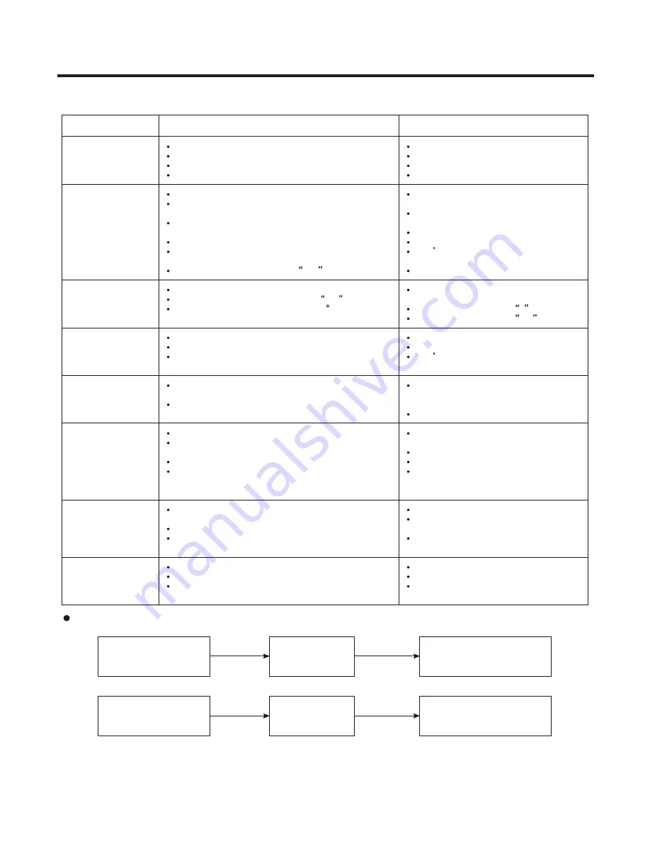
4-2 SERVICE DIAGNOSIS CHART


Cooling is

impossible.

Is the power cord unplugged from the outlet?

Checked if the power S/W is set to OFF.

Check if the fuse of power S/W is shorted.

Measure the voltage of power outlet.

Check if the set is placed close to wall.

Check if the set is placed close to stove, gas,

cooker and direct rays.

Is the ambient temperature high or the room door

closed?

Check if putting in hot foods foods.

Did you open the door of the set too often or check

if the door is closed up?

Check if the Control is set to Min .

Are foods placed in cooling air outlet?

Check if the Display LED is set to 0-1 .

Is the ambient temperature below 5 C.

Is watery foods kept?

Check if putting in hot foods.

Did you open the door of the set too often or check

if the door is closed up.

Check if ambient temperature and humidity of

surrounding air are high.

Is the gap in the door packed?

Is the set positioned in a firm and even place?

Does any unnecessary objects exists in the back

side of the set?

Check if the Drip tray is not firmly fixed?

Check if the cover of mechanical room in below

and back side is taken out.

Check if the door packing becomes dirty by filth

such as juice.

Is the set positioned in a firm and even place?

Is too much food putted in the set?

Check if the inside of the set becomes dirty.

Did you keep smelly foods without wrapping?

It smells plastic.

Plug to the outlet.

Set the switch to ON.

Replace a regular fuse.

If voltage is low, wire newly.

Place the set with the space of about

10cm

Place the set apart from these heat

appliances.

Make the ambient temperature below.

Put in foods after they get cold cold.

Don t open the door too often and

close it firmly.

Set the control to mid-position.

Place foods in high temperature

section. (Front part)

Set the Display LED to 3 .

Set the Display LED to 5-6 .

Seal up watery foods with wrap.

Put in foods after they get cold.

Don t open the door too often and

close it firmly.

Wipe dew with a dry cloth. This

happening is solved in low temperature

and humidity naturally.

Fill up the gap.

Adjust the leveling screw, and position

in the firm place.

Remove the objects.

Fix it firmly on an original position.

Place the cover at an original position.

Clean the door packing.

Position in the firm place and adjust the

adjust screw.

Keep foods not to reach the door.

Clean the inside of the set.

Wrap smelly foods.

The new products smell plastic, but it is

removed after 1-2 weeks.

Cooling ability is

poor.

Foods in the

refrigerator

are frozen.

Dew or ice forms in

the chamber of the

set set.

Dew forms in the

Out Case.

Abnormal noise

generates.

To close the door

is not handy.

Ice and foods

smell unpleasant.

In addition to the items describes left, refer to the following to solve the complaint.

Check if dew forms

in the freezer.

Replace the

components of

defrosting circuit.

Check refrigerator

Cycle.

The cycle is

faulty.

Repair the cycle.

COMPLAINT

N

O

I

T

C

A


E

C

I

V

R

E

S

D

E

K

C

E

H

C


E

B


O

T


S

T

N

I

O

P

Copyright © 20

 LG Electronics Inc. All rights reserved.

Only training and service purposes. 

18

Summary of Contents for LTCS20020W

Page 1: ... modification copying or transmission of this Service Manual is STRICTLY PROHIBITED unless you have obtained the prior written consent of the LG Electronics entity from which you received this Service Manual The material covered by this prohibition includes without limitation any text graphics or logos in this Service Manual Copyright 2020 LG Electronics Inc All rights reserved Only training and s...

Page 2: ... may cause frost bite 6 Prevent water from spiling on to electric elements or the machine parts 7 Before tilting the refrigerator remove all materials from on or in the refrigerator 8 When servicing the evaporator wear gloves to prevent injuries from the sharp evaporator fins 9 Service on the refrigerator should be performed by a qualified technician Sealed system repair must be performed by a CFC...

Page 3: ... M G 1 1 0 N H M V 29 9 x 33 9 x 66 1 in STAINLESS LTCS20020W 91 6 k g 20 cu ft R 600a T em perate N 115V 60H z Shelf T ray m eat T ray egg B as k et Q uantity Lam p Shelf D es fro s ting D ev ice C as e M aterial D o o r M aterial H andle T ype B as k et Q uantity Ice T ray B ank C o v er T V Lam p C o ndens er Lubricanting O il D rier C apillary T ube F irs t D efro s t D efro s t C ycle C o o l...

Page 4: ...tor you have purchased may have some or all of the i tems listed below The locations of the features shown below may not match your model Custom Cube Icemaker A Refrigerator Light LED F Refrigerator Temperature Control D Shelves E Freezer Shelf B A B C D E F H J G I L G Crispers H Freezer Door Bins I Dairy Bin J Refrigerator Door Bins Freezer Temperature Control C 2 PARTS IDENTIFICATION 4 ...

Page 5: ...death or serious injury 1 Removing Freezer Door Gently pry off the Top Hinge Cover with a flat head screwdriver and remove it See Fig 1 Using 10 mm or 3 8 inch socket wrench remove the three bolts and lift the Top Hinge See Fig 2 Set parts aside Lift freezer door slightly and remove it See Fig 3 Set parts aside 2 Removing Refrigera tor Door Loose and remove the two bolts and the screw to remove the...

Page 6: ...ousing Use the two bolts and the screw to refasten the middle hinge with the refrigerator housing See Figure 9 4 Replacing Freezer Door Set the freezer door onto the Middle Hinge pin Figure 10 Place upper hinge in the top of the freezer door and line up the hinge with the holes in top of refrigerator Use the three bolts to fasten the hinge See Figure 11 Carefully force the top hinge cover back int...

Page 7: ...e other side of the door keeping the same orientation and move the Hinge Pin Insert into the hole on the left side of the bracket Reversethe Door Closer Stop by flipping it over Place it on top of the Hinge Pin Inse rt Bracket and tighten both down with the screw Pry off the cover on the top left side of the refrigerator to uncover the screw holes Set the freezer door and top hinge parts to the sid...

Page 8: ... is still attached Using a 3 8 socket wrench with a 2 Inch extension and screwdriver loosen the two bolts and one screw and remove the Bottom Hinge from right side of the housing Remove the Decorative Caps on the bottom of the refrigerator housing You will need these holes for the Bottom Hinge Move the Bottom Hinge to the left side of the housing keeping the same orientation and reattach with the ...

Page 9: ...r and middle hinge and re attach Hinge Pin to Hinge Bracket with a socket wrench NOTE Bracke NOTE The Door Closer Stop is only presented on some t has been flipped but Hinge Pin stays in the same orientation with its hexagonal end facing upward Insert the Decorative Screw into the outer hole on the right side of the housing Attach cover on the right side Cover is force fitted REATTACHING THE DOORS P...

Page 10: ... to adjust it to the inclination you would like NOTE Having someone push against the top of the refrigerator takes some weight off the leveling screws This will make it easier to adjust the screws 3 Open both doors again and check to make sure that they close easily If not tilt the refrigerator slightly more to the rear by turning both Leveling Screws clockwise It may take several more turns and y...

Page 11: ...king the voltage on COMP side 3 4 2 Open back cover 2 Check wheter C Fan operates 1 CHECK COMP and Discharge PIPE temperature Check the number of LED blinking Refer to the next chapter for actions for each number of LED blinking If COMP is normal it will not blink Test Mode Button Copyright 20 LG Electronics Inc All rights reserved Only training and service purposes Check disconnection in OLP and ...

Page 12: ...B Is Comp in operation Check Comp Check C Compressor SVC Manual 1 Check LED Trip 1 Separate PCB COVER and check number of LED blinking 2 Verify the actions for each number of blinking Check when it is not RESET Before turning off the power of the refrigerator 3 Write the service information according to the number of LED blinking 4 Write SVC information and check again after power reset Refer to t...

Page 13: ...mes repeated Blink Blink Blink Blink Blink Blink Blink Off Blink Blink Blink Blink Blink Blink Blink Off Repeated PCB defect part IPM 1 Check normal operation after power reset 2 If same error occurs after 1 replace PCB 2 LED 1 time repeated Blink Off Blink Off Blink Off Blink Off Blink Off Blink Off Blink Off Blink Off Repeated AD offset Error 1 Check normal operation after power reset 2 If same ...

Page 14: ...ection logic LED blinking 1 time AD offset Error Is it out of Spec 2 2 2 8V Replace PCB Power Reset Objective to detect Motor voltage or current sensing defect Actions check CC310 voltage and if it is outside 2 2 2 8V replace PCB Copyright 20 LG Electronics Inc All rights reserved Only training and service purposes 14 ...

Page 15: ...ere is no significant difference between the temperature inside the refrigerator and the set temperature there is no problem in PCB Compressor or Cycle 2 If it blinks 6 times and problem such as no cooling occurs it means cycle leakage or cycle clogged moisture trash Cause Cycle leakage or clogging excessive Compressor temperature increase compressor piston locked PCB IPM device burned due to Cond...

Page 16: ... Actions for each TRIP and the number of LED blinking F F O k n i l B Blink Blink Blink Blink Blink Blink Cause IPM Short defect burned or damaged Objective Protection of the over current caused by IPM short or defect Actions Visual verification of IPM burn when COMP is not in operation Check whether there is a short circuit in U V or W part Replace PCB U GND GND P N EBR807574 Copyright 20 LG Elec...

Page 17: ...sn t run Much frost are sticked to the EVAPORATOR Replace each component Replace each component Replace each component Multi Tester Motor resistance Compressor BMG110NAMV ambient temperature or operation condition Cooling ability is poor Check COMPRESSOR HARNESS Measure COMP connector resistance Power Common Check insulation destruction measure the resistance between the COMP power connector and t...

Page 18: ... Replace a regular fuse If voltage is low wire newly Place the set with the space of about 10cm Place the set apart from these heat appliances Make the ambient temperature below Put in foods after they get cold cold Don t open the door too often and close it firmly Set the control to mid position Place foods in high temperature section Front part Set the Display LED to 3 Set the Display LED to 5 6...

Page 19: ... point also shows infinity or several hundred disassemble Cover PTC of the Compressor connector and check the locking status of the terminal at D point in the figure If it is normal check the contact status of O L P fixed inside Cover PTC The problem in O L P may be judged by the resistance values at both ends of O L P If both ends of O L P are measured and the resistance value shows 5 or less it ...

Page 20: ...e pressure of dry air must be more than 12 16Kg cm2 2 Temperature must be more than 20 70 C 3 Keep the pressure to 12 6Kg cm2 also when substituting dry air for Nitrogen Gas 1 Check if gas leaks with soapy water 2 Replace Quick Coupler in case of leakage Put all Joint Pipe in a clean box and cover tightly with the lid so that dust or humidity is not inserted Recommend H34 containing 34 Ag in the S...

Page 21: ...6 4 3 2 1 5 YL PR BO RD BN BL GN YL R HEATER RESISTENCIA R WATER VALVE VALVULA DE AGUA PILOT VALVE VALVULA PILOTO FUSE M FUSIBLE M FUSE M FUSIBLE M DEF HEATER RESISTENCIA DE DESHIELO ICE VALVE VALVULA DE HIELO A C D B EARTH PART TIERRA CON5 1 2 3 4 5 6 7 8 9 10 11 12 RD BK PR YL BN BL GY SB M F FAN MOTOR M C FAN MOTOR 1 2 3 4 5 6 7 WH SB SB PR CON11 WH PR 5 4 3 2 1 PWB ASSEMBLY SMART BUZZER CON1 D...

Page 22: ...connection condition Advise customer that power supply needs to be checked by an Supply voltage rating with 10 Check resistance of two terminals in PTC Starter Check resistance of two terminals in OLP Check the power supply under load Compressor attempting to re start after being off for 5 minutes Check resistance of PTC Starter Check OLP Check starting state Check resistance of motor compressor C...

Page 23: ...al operation of Compressor is not working or poor Separate OLP from Compressor and check resistance value between two termianls of OLP with a Tester Figure 2 Check another electriccomponent Replace OLP Figure 2 23 ...

Page 24: ... Shorted Lack of capacity Replace indicated component Advise customer that the Power supply needs to be checked by an electrician Replace indicated component Cause Check voltage at starting devices Check current flowing in sub coil of Compressor Check rating of OLP Fan motor doesn t run Heavy frost buildup on EVAPORATOR Wire is open or shorted Coil is shorted or open Open Open Replace Defrost Heat...

Page 25: ...eck air flow across condenser 3 Evaporator fan motor not operating 3 Check evaporator fan motor and wiring circuit 4 Internal air flow blocked 4 Check air ducts 5 Sensor not operating properly 5 Check refrigerator and freezer sensors 6 Door not sealing 6 Check for proper door seal 7 Evaporator frosted up 7 Check defrost circuit components 8 Sealed system related problem 1 Open in defrost circuit 1...

Page 26: ... frost forms in inlet only temperature refrigerant level NO COMP No compressing RESSION operation is not heard and there is temperature pressure part of the no frost compressor CAUSE TEMPERATURE OF THE COMPRESSOR REMARKS STATE OF THE UNIT STATE OF THE EVAPORATOR E G A K A E L T S U D Y B D E T C I R T S E R E V I T C E F E D N O I S S E R P M O C Check sealed system for leak Check if compressor ru...

Page 27: ...doesn t reach the 50 F 10 C in 1 hour the defrost mode is malfunctioning Refer to the defect diagnosis function Defrosting won t function if the sensor if defective wires are cut or short circuited 8 1 3 Electrical Parts Operation in Sequence Electrical parts such as COMP defrost heater freezer FAN etc Operate in the following order to prevent noise and parts damage Several parts are started at th...

Page 28: ...roduced and it works as follows 1 Defrosting starts each time the compressor running time reaches between 7 50 hours and 50 hours according to door open time 2 For initial power on or for restoring power defrosting starts when the compressor running time reaches 4 hours 3 Defrosting stops if the sensor temperature reaches 10 C or more If the sensor doesn t reach 10 C in 2 hours the defrost mode is...

Page 29: ...ld down TEMP AJUST button ON OFF NO Item Error Code Contents Product Operation Status in Failure Compressor Freezer Motor Defrost Heater R1 R2 R3 R4 R5 1 Failure of Refrigerator Sensor Ref Sensor Open or Short circuit wire 15min ON 15 min OFF 15min ON 15 min OFF Normal 2 Failure of Defrost Sensor Defrost Sensor Open or Short circuit wire Normal Normal No defrost 3 Failure of Room Temperature Senso...

Page 30: ...r failure is detected while in the test mode the test mode is cleared and the error code is displayed 6 While an error is detected the test mode will not be activated even if the test button is pushed 1 Comp OFF 2 Freezer fan OFF 3 Defrosting heater ON 4 Temperature display part show as bellows Reset if the temp of the defrosting sensor is 10 C or above LED Check Mode When the ADJUST TEMP button i...

Page 31: ...le doesn t work 7 Refrigerator Room LED Module doesn t work 8 Poor cooling in Refrigerator room 9 Over cooling in Refrigerator room 10 Freezer BLDC FAN Motor Error 11 Cooling BLDC FAN Motor Error 1 Temperature compensation 2 TEST MODE and Removing TPA 3 TEMPERATURE CHART REF AND DEFROST SENSOR 4 TEMPERATURE CHART RT SENSOR CONTENTS Copyright 20 LG Electronics Inc All rights reserved Only training ...

Page 32: ...N 8 Sensors LED Lightning and door switch CON 10 CON 202 Programming Port CON 11 Dispenser Switch Smart Buzzer Optional and Dispenser LED Optional CON201 OLP CON 7 Touch Display PCB CON 9 Ice Maker twisting CON8 CON11 CN1 CON6 CON5 CON201 CON1 CON102 2 BOARD SYSTEM DIAGNOSIS INTELLIGENT SDS P N EBR64730407 Copyright 20 LG Electronics Inc All rights reserved Only training and service purposes 32 ...

Page 33: ...Part Name 1 1 MAIN PCB Picture PCB PJT QT 20 220 230V Power Cord PJT Plug C4 220V P N EBR807574 P N EAD61445250 Copyright 20 LG Electronics Inc All rights reserved Only training and service purposes 33 ...

Page 34: ...2 P N EBR59400503 1 2 DISPLAY PCB LED Lighting Basic Models Tact and Inner Display Dispenser Models Tact and Inner Display P N ACQ89591801 R Room LED Module Copyright 20 LG Electronics Inc All rights reserved Only training and service purposes 34 ...

Page 35: ...104 F 40 C RESISTANCE 225 1 169 8 129 3 99 30 76 96 60 13 47 34 37 55 30 24 13 19 53 15 91 13 03 10 74 8 89 7 40 6 20 VOLTAGE 4 48 V 4 33 V 4 641 V 4 54 V 4 425 V 4 287 V 4 128 V 3 948 V 3 75 V 3 535 V 3 307 V 3 070V 2 829 V 2 589 V 2 354 V 2 128V 1 914 V Check for loose connection in CON8 2 1 Unplug connector from CON8 2 Check resistance in wires Brown to Brown 3 Plug in CON8 check voltage in wir...

Page 36: ... back to the main PCB if they are open between the main PCB and connector it will be necessary to replace the refrigerator Check the Temp and resistance Table 1 Result SVC Action Check for loose connection in CON8 2 1 Unplug connector from CON8 2 Check resistance in wires White to White Firmly plugged Loose Go to step 2 Plug firmly then check again Problem persist YES Go to step 2 NO Explain to cu...

Page 37: ...or it will be necessary to replace the refrigerator Check the Temp and resistance Table 2 Result SVC Action 1 Check for loose connection in CON8 2 1 Unplug connector from CON8 2 Check resistance in wires Orange to Orange 3 Check for loose connection in evaporator heater connector 4 1 Unplug evaporator heater connector 2 Check resistance in wires Orange to Orange Firmly plugged Loose Go to step 2 P...

Page 38: ... S t l u s e R w o l f g n i k c e h C o N Fuse M Def Heater Def Sensor 0 0 1 Check the Door Gasket 2 Check the Defrost control part Fuse M Defrost Heater 3 Input Test 2 Mode Push the button 2 times 4 Check voltage in wires Brown to Blue in connector CON2 5 Release the test mode Push the button 1 times normal 6 Check voltage in wires Brown to Blue in connector CON2 COLDEST COLD Copyright 20 LG Ele...

Page 39: ...c switch replace the switch If there is not continuity go to step 3 Door Magnetic Switch Status Result SVC Action Status Result SVC Action Normal Infinity Resistence Place the magnet near to the magnetic switch 0 Disconnect the magnetic switch and confirm if continuity between the terminals exists or not Is there continuity when you close magnetic switch with the magnet placed on the door NOTE For...

Page 40: ...ion Closed Open 12 V Other 0 V Other Normal Change the PCB Normal Change the PCB Status Result SVC Action 4 1 Unplug connector from CON8 2 Check resistance in wires Gray to Gray 5 Plug in CON8 check voltage in wires Gray to Gray 6 Check voltage in wires from CON8 Red to Black 7 Check voltage in Refrigerator LED Connector Open Closed 12 V Other 0 V Other Change Freezer LED Change the PCB Normal Cha...

Page 41: ...o windy SVC Action Go to the 4 Check the Fan motor Next page Status Cold Not cold SVC Action Normal Check the Compressor And sealed system 4 Check the air temperature Cold or not 1 1 Unplug connector from CON8 2 Check resistance in wires White to White Release Motor Point Result SVC Action 5 Check the Fan motor Rotate fan using your hand It feel sticky change the motor cause of ice or rust inside ...

Page 42: ... F Result SVC Action Temperature 23 F C 32 F C 41 F C 50 F C 59 F C Result 38 30 24 19 5 16 Status Windy No windy SVC Action Go to the 4 Check the PCB Status Windy No windy SVC Action Change the PCB It s normal 4 Input Test 2 Mode and Check the air flow push the button 1 time 1 1 Unplug connector from CON8 2 Check resistance in wires White to White Copyright 20 LG Electronics Inc All rights reserv...

Page 43: ...Test 1 Mode push the button 1 times 2 Open the freezer door and Check the Air flow While an error code is displayed the fan is not working d n a h r u o y g n i s u n a f e t a t o R r o t o m n a F e h t k c e h C 3 It feel stuck or locked up change the motor CON5 CON5 4 Check the FAN Motor Voltage in wires Brown to Blue 5 Check the FAN Motor Feedback Voltage in wires Blue to Gray Status COLDEST ...

Page 44: ...on Input Test 1 Mode push the button 1 times d n a h r u o y g n i s u n a f e t a t o R r o t o m n a F e h t k c e h C 3 It feel stuck or locked up change the motor 2 Check the Fan motor rotate in machine room While an error code is displayed the fan is not working 4 Check the FAN Motor Voltage in wires Red to Black 5 Check the FAN Motor Feedback Voltage in wires Black to Purple COLDEST COLD Cop...

Page 45: ...ut the jump wire on the Main PCB CUT OPTION Temperature compensation Over cooling compensation Poor cooling compensation JCR1 JCR2 JCR3 JCR4 Refrigerator Room 3 Reference JCR1 cuts 1 JCR2 cuts 1 JCR3 cuts 1 JCR4 cuts 1 Copyright 20 LG Electronics Inc All rights reserved Only training and service purposes 45 ...

Page 46: ...urance TPA 1 time Comp ON F fan ON Defrost Heater OFF Display ALL ON 2 times Comp OFF F fan OFF Defrost Heater ON 2 displayed Main PCB AC TPA DC TPA 2 TEST MODE and Removing TPA All LED turn on TEST MODE 2 After measure the values you should put in the TPA again Copyright 20 LG Electronics Inc All rights reserved Only training and service purposes 46 ...

Page 47: ... 282B S13 283B 120A 120A 105A 318A 323B 420A 405G 405D 329C 319D 319F 106A 106A 305B 305C 315A 305C 305B 10 EXPLODED VIEW 317A 120A 501B 279A 120B 158C 503G 410A B01 S38 501A 406B 619B Copyright 2020 LG Electronics Inc All right s reserved Only training and service purposes 327A 120E 47 EV ...

Page 48: ...404Z 149F S16 48 EV FREEZER PARTS Copyright 2020 LG Electronics Inc All right s reserved Only training and service purposes 405C 404A 319E 330B 405F S01 332A 284A 329A 110D 332B 282X 284B 284E ...

Page 49: ...167B 143A 151A 151A 154A 151D 151C 155B 49 EV REFRIGERATOR PARTS Copyright 2020 LG Electronics Inc All right s reserved Only training and service purposes ...

Page 50: ...241A 230A 231A 233A 281E 241C 241C 205A 205A 200A 201A 203A 212G 286A 210B 210C 286A 210A 50 EV DOOR PARTS Copyright 2020 LG Electronics Inc All right s reserved Only training and service purposes ...

Page 51: ...Mar 2020 MFL71772901 ...

Reviews: