16 INSTALLATION
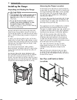
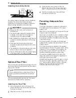
Installing the Anti-tip Device
Anti-tip
bracket
Wall plate
Screw must
enter wood or
concrete
The anti-tip bracket is packaged with an installation
template. The instructions include necessary
information to complete the installation. Read and
follow the range installation instruction sheet.
WARNING
•
Range must be secured with an approved
anti-tip device.
•
The range could be tipped by standing, sitting
or leaning on an open door if the range or
anti-tip device is not properly installed.
•
After installing the anti-tip device, verify that it is
in place by carefully attempting to tilt the range
forward.
•
This range has been designed to meet all
recognized industry tip standards for all normal
conditions.
•
The installation of the anti-tip device must meet
all local codes for securing the appliance.
•
The use of this device does not preclude tipping
of the range when not properly installed.
Optional Rear Filler
If the counter does not bridge the opening at the rear
wall the rear filler kit, that is provided with the slide in
range, will be needed.
NOTE
If the countertop depth is greater than 25" there
will be a gap between the filler kit and the back
wall.
If the countertop depth is less than 24", the control
panel will not sit flush with the countertop.
Installing the Rear Filler
1
Using a screwdriver, remove the upper four
screws that attach the rear bracket and loosen
the lower two screws.
2
Place the rear filler on the rear bracket.
3
Tighten the two lower screws on the rear
bracket. Insert one of the screws removed in
step 1 in the slot at each end of the rear filler.
4
Store the remaining two screws with these
instructions for future use.
Providing Adequate Gas
Supply
Your range is designed to operate at a pressure of
5" of water column on natural gas or 10" of water
column on LP.
Make sure you are supplying your range with the type
of gas for which it is configured.
This range is convertible for use on natural or LP gas.
When using this range on LP gas, conversion must
be made by a qualified LP installer before attempting
to operate the range.
For proper operation, the pressure of natural gas
supplied to the regulator must be between 5" and 13"
of water column.
For LP gas, the pressure supplied to the regulator
must be between 10" and 13" of water column. When
checking for correct operation of the regulator, the
inlet pressure must be at least 1" more than the
operating (manifold) pressure as given above.
The pressure regulator located at the inlet of the
range must remain in the supply line regardless of
which type of gas is being used.
A flexible metal appliance connector used to connect
the range to the gas supply line should have an I.D.
of
5
/
8
" and a maximum length of 5 feet. In Canada,
flexible connectors must be single wall metal
connectors less than 6 feet in length.

