


3-3
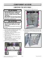
9. Remove a cooktop plate assembly (See the page
3-6) and remove 4 screws from side panel.
10. Remove 4 screws from the controller assembly
(back guard R/L)
11. Remove 6 screws from the controller assembly.
12. For serving the KEY Membrane, the controller sub
assembly should be separated in whole. Both
Control-panel and KEY Membrane are 1 service
part.
COMPONENT ACCESS
Summary of Contents for LRE3194BD
Page 39: ...5 2 Composition of control Key Matrix ...
Page 42: ...5 5 Composition of control Cook top display PCB Key Pad ...
Page 71: ...12 3 BAKE COOK WARM PROOF CONV BAKE CONV ROAST SELF CLEANING CR Warming Zone ...
Page 72: ...12 4 RR Cook top Element LR Cook top Element LF Cook top Element RF Cook top Element ...
Page 75: ... EV CONTROLLER PARTS 2381 2031 2050 2006 2048 2037 2042 2036 3006 2034 2041 2075 ...
Page 76: ... EV COOKTOP PARTS 3057 3014 3056 3302 3301 3303 3303 3401 3022 3204 3401 3204 3204 3204 ...
Page 79: ......