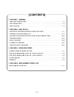
- 1-2 -
SECTION 1. GENERAL
❏
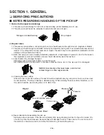
SERVICING PRECAUTIONS
■
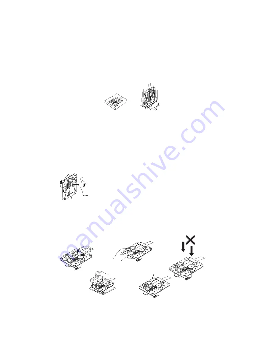
NOTES REGARDING HANDLING OF THE PICK-UP
1. Notes for transport and storage
1) The pick-up should always be left in its conductive bag until immediately prior to use.
2) The pick-up should never be subjected to external pressure or impact.
2. Repair notes
1) The pick-up incorporates a strong magnet, and so should never be brought close to magnetic materials.
2) The pick-up should always be handled correctly and carefully, taking care to avoid external pressure and
impact. If it is subjected to strong pressure or impact, the result may be an operational malfunction and/or
damage to the printed-circuit board.
3) Each and every pick-up is already individually adjusted to a high degree of precision, and for that reason
the adjustment point and installation screws should absolutely never be touched.
4) Laser beams may damage the eyes!
Absolutely never permit laser beams to enter the eyes!
Also NEVER switch ON the power to the laser output part (lens, etc.) of the pick-up if it is damaged.
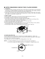
5) Cleaning the lens surface
If there is dust on the lens surface, the dust should be cleaned away by using an air bush (such as used
for camera lens). The lens is held by a delicate spring. When cleaning the lens surface, therefore, a cot-
ton swab should be used, taking care not to distort this.
6) Never attempt to disassemble the pick-up.
Spring by excess pressure. If the lens is extremely dirty, apply isopropyl alcohol to the cotton swab. (Do
not use any other liquid cleaners, because they will damage the lens.) Take care not to use too much of
this alcohol on the swab, and do not allow the alcohol to get inside the pick-up.
Storage in conductive bag
Drop impact
NEVER look directly at the laser beam, and don’t let
contact fingers or other exposed skin.
Magnet
How to hold the pick-up
Conductive Sheet
Cotton swab
Pressure
Pressure
Summary of Contents for LM-U360
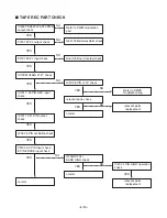
Page 7: ... 1 6 ...
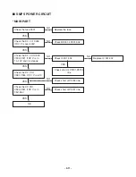
Page 20: ... 2 13 INTERNAL BLOCK DIAGRAM of ICs UTC MC4580 PIN CONFIGURATION TEST CIRCUIT ...
Page 21: ... 2 14 FAN8082D Internal Block Diagram ...
Page 22: ... 2 15 BU2090 Block diagram ...
Page 23: ... 2 16 BA3308 BA3308F BLOCK DIAGRAM BA3308 BA3308F ...
Page 24: ... 2 17 HT1200 4 SYSTEM BLOCK DIAGRAM ...
Page 25: ... 2 18 HT1200 4 FUNCTIONAL BLOCK DIAGRAM ...
Page 26: ... 2 19 CS5340 BLOCK DIAGRAM BU4052 BLOCK DIAGRAM ...
Page 27: ... 2 20 HA12237F BLOCK DIAGRAM ...
Page 28: ... 2 21 PT6324 BLOCK DIAGRAM ...
Page 43: ......
Page 53: ...2 54 2 55 PRINTED CIRCUIT DIAGRAMS MAIN P C BOARD TOP VIEW ...
Page 54: ...2 56 2 57 MAIN P C BOARD BOTTOM VIEW ...
Page 55: ...2 58 2 59 FRONT P C BOARD ...
Page 56: ...2 60 2 61 SMPS P C BOARD DECK P C BOARD BOTTOM VIEW TOP VIEW ...
Page 57: ...2 62 2 63 CD P C BOARD TOP VIEW ...
Page 58: ...2 64 2 65 CD P C BOARD BOTTOM VIEW ...
Page 59: ......
Page 65: ... 3 10 ...


