3-9
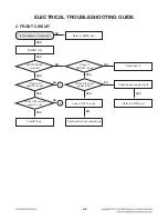
FRONT CIRCUIT
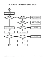
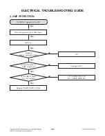
ELECTRICAL TROUBLESHOOTING GUIDE
1
2
Refer to power(SMPS).
Refer to power(SMPS).
Reconnect it.
Refer to MICOM circuit.
Replace R306~R309.
Check REM circuit
Refer to MICOM circuit.
Resolder or Replace IR301.
Check
if the power part of the front
is ok?
Check
if thepower part of the front
is ok?
Check if CON303 is ok?
Check if the remote
control waveform of CON301
pin3 is ok?
Check if R306~R309 ok?
Check if REM
voltage is ok(3.3 V)?
NO
NO
NO
NO
NO
NO
YES
YES
YES
YES
YES
YES
Summary of Contents for LAS350B
Page 9: ...2 2 ...
Page 11: ...A900 2 SUBWOOFER SECTION ...
Page 13: ...2 8 ...
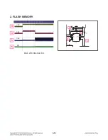
Page 28: ...3 15 2 FLASH MEMORY FIG 2 VCC CS CLK DO 3 4 5 6 VCC CS CLK DO 5 6 4 3 ...
Page 30: ...3 17 4 USB FIG 4 1 USB_5V 11 FIG 4 2 USB D 12 FIG 4 3 USB D 13 11 EC405 100uF 16V C475 12 13 ...
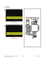
Page 32: ...3 19 6 OPTICAL FIG 6 1 OPT_IN 17 FIG 6 2 OPT_DET 18 17 18 ...
Page 37: ...3 24 ...
Page 47: ...3 44 3 43 2 MAIN P C BOARD DIAGRAM TOP VIEW BOTTOM VIEW ...
Page 49: ...3 48 3 47 ...


