4-11
DECK MECHANISM DISASSEMBLY
Washer (W1)
Gear Drive
Gear Cam
Gear Connector
Hole (A)
Hole (B')
Hole (B')+(B)
Chassis
Hole (A')+(A)
Gear Cam
Gear Connector
Brake Assembly Capstan
(For 4HD Models)
Hole (A')
Bracket Assembly
L/D Motor
H1
H2
Hole (B)
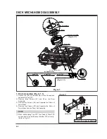
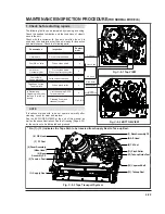
Fig. A-8
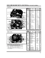
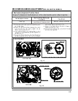
27. Gear Drive (Fig. A-8-1)/
Gear Cam (Fig. A-8-2)/
Gear Connector (Fig. A-8-3)
1) Remove the Washer(W1) and lift up the Gear Drive.
2) Lift up the Gear Cam.
3) Lift up the Gear Connector.
(1) When reassembling, confirm that the Hole (A) of the
Gear Connector is aligned to the Hole (A') of the Chassis
(Fig. A-8-3).
(2) When reassembling, confirm that the Hole (B) of the
Gear Cam is aligned to the Hole (B') of the Chassis (Fig.
A-8-2).
(3) When reassembling, confirm that the (C) part of the Gear
Cam is aligned to the (D) part of the Gear Drive as shown
Fig. B-3
28. Bracket Assembly L/D Motor (Fig. A-8-4)
1) Unhook the three Hooks(H1),(H2) and push down the
Bracket Assembly L/D Motor.
NOTE
Gear Cam (C)
Gear Drive (D)
Hook (H1), (H2)
Chassis
(Fig. B-3)
(Fig. A-8-1)
(Fig. A-8-2)
(Fig. A-8-3)
(Fig. A-8-4)
Summary of Contents for KB-14P2B
Page 22: ...3 7 BLOCK DIAGRAM ...
Page 23: ...VCD BLOCK DIAGRAM 3 8 ...
Page 24: ...VIDEO AUDIO BLOCK DIAGRAM 3 9 ...
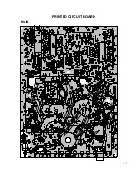
Page 32: ...3 17 PRINTED CIRCUIT BOARD MAIN ...
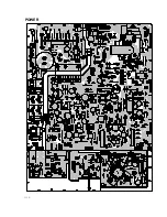
Page 33: ...3 18 POWER ...
Page 79: ...PB A REC A PB V REC V P No 3854VA0070A S Date 2001 02 10 CIRCUIT DIAGRAM OF MV 995B ...

