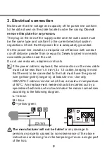

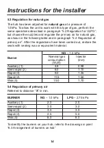
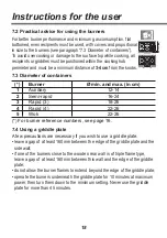
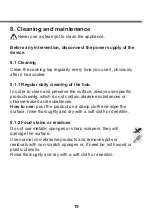
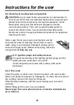

5
Instructions for the installer
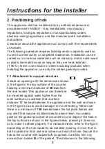
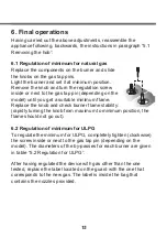
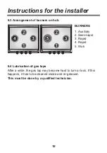
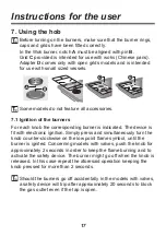
2. Positioning of hob
This appliance shall be installed only by authorized persons in
accordance with AS5601 - Gas Installations, any statutory
regulations, local gas regulations, municipal building codes,
electrical wiring regulations, and the manufacturer's installation
instructions.
Clearance around the appliance must comply with the requirements
of AS5601.
The following operation requires building and/or carpentry work so
must be carried out by a competent tradesman. Installation can be
carried out on various materials such as masonry, metal, solid wood
or plastic laminated wood as long as they are heat resistant
(T 90°C). Never use silicone or other insulating products when
installing the appliance; use only the rubber gasket provided.
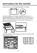
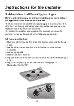
2.1 Attachment to support structure
Create an opening with the dimensions shown
in the figure in the top surface of the counter,
keeping a minimum distance of
50 mm
from
the rear border. This appliance can therefore
be mounted against walls higher than the
work surface on condition that a certain
distance “
X
” be kept between the appliance and the wall as shown
in the figure so as to avoid damage from overheating. Make sure
there is a minimum of
750 mm
between the hot plate flames and
any shelf that may be installed directly above them. Accurately
position the gasket provided all around the outer edge of the hole in
the top surface as shown in the figures below, pressing it down so
as to make it adhere properly. For measurements, refer to the figure
depending on the hob model to be installed, bearing in mind that in
both models the front and rear sides must skim the hole. Secure the
hob to the counter with brackets
A
(supplied). Carefully trim any
excess from border
B
of the gasket. The distances in the following