6-5 REFRIGERATION CYCLE
- 16 -
▼
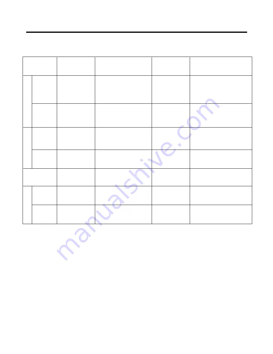
Troubleshooting Chart
PARTIAL
Freezer
Low flowing sound of
A little higher
• Refrigerant level is low due
LEAKAGE
compartment and
Refrigerant is heard and
than ambient
•
to a leak.
Refrigerator don't
frost forms in inlet only.
temperature.
• Normal cooling is possible by
cool normally.
•
restoring the normal amount of
•
refrigerant and repairing the leak.
COMPLETE
Freezer
Flowing sound of refrigerant
Equal to ambient
• No discharging of Refrigerant.
LEAKAGE
compartment and
is not heard and frost isn't
temperature.
• Normal cooling is possible by
Refrigerator don't
formed.
•
restoring the normal amount of
cool normally.
•
refrigerant and repairing the leak.
PARTIAL
Freezer
Flowing sound of refrigerant
A little higher
• Normal discharging of the
CLOG
compartment and
is heard and frost forms
than ambient
•
refrigerant.
Refrigerator don't
in inlet only.
temperature.
• The capillary tube is faulty.
cool normally.
WHOLE
Freezer
Flowing sound of refrigerant
Equal to ambient
• Normal discharging of the
CLOG
compartment and
is not heard and frost isn't
temperature.
•
Refrigerant.
Refrigerator don't cool. formed.
MOISTURE
Cooling operation
Flowing sound of refrigerant
Lower than
• Cooling operation restarts
CLOG
stops periodically.
is not heard and frost melts.
ambient
•
when heating the inlet of the
temperature.
•
capillary tube.
COMP-
Freezer and
Low flowing sound of
A little higher
• Low pressure at high side
RESSION
Refrigerator
refrigerant is heard and
than ambient
•
of compressor due to low
don't cool.
frost forms in inlet only.
temperature.
•
refrigerant level.
NO COMP-
No compressing
Flowing sound of refrigerant
Equal to ambient
• No pressure in the high
RESSION
operation.
is not heard and there is
temperature.
•
pressure part of the
no frost.
•
compressor.
CAUSE
TEMPERATURE
OF THE
COMPRESSOR
REMARKS
STATE OF
THE UNIT
STATE OF THE
EVAPORATOR
LEAKAGE
CLOGGED
B
Y
D
UST
DEFECTIVE
COMPRESSION
Summary of Contents for GR-F218
Page 11: ...5 CIRCUIT DIAGRAM 11 ...
Page 37: ...8 5 MAIN PWB ASSEMBLY AND PARTS LIST 8 5 1 Main PWB Assembly 37 ...
Page 38: ...8 5 2 Replacement Parts List 38 ...
Page 39: ...8 5 3 PWB Assembly Display And Parts List 39 ...
Page 40: ...8 5 4 Circuit Diagram of Display 40 ...
Page 41: ...8 6 PWB DIAGRAM 8 6 1 PWB Main Assembly 41 ...
Page 42: ... 42 ...


