
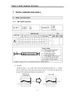


Chapter 7 Buffer read/write instructions
7 - 11
Remarks
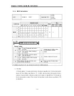
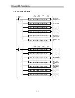
The structure of ‘SS’ (Link status) of RPUT/RGET instruction is as following;
bit15
bit14
bit13
bit12
bit11
bit10
bit9
bit8
bit7
bit6
bit5
bit4
bit3
bit2
bit1
bit0
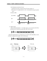
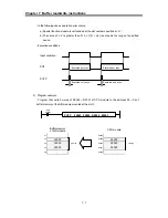
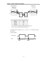
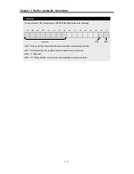
Bit 0 : Turns on during 1 scan after the communication is completed normally.
Bit 1 : Turns on during 1 scan after a communication error is occurred.
Bit 2 ~ 7 : Not used
Bit 8 ~ 15 : When the bit 1 turns on, the corresponding error code is stored.
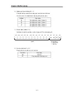
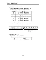
Error code
Error
Done


