background image

A14

Troubleshooting

No image appears

Check the following before calling for service.

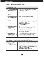
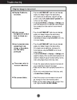
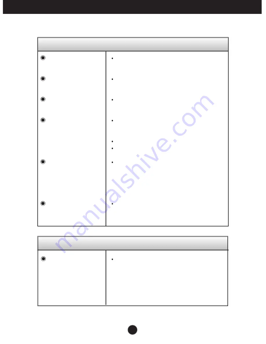
No image appears

Is the power cord of the
display connected?

Is the power indicator
light on?

Is the power on and the
power indicator blue?

Is the power indicator
amber?

Do you see an "INPUT
SIGNAL OUT OF
RANGE" message on
the screen?

Do you see a "NO
SIGNAL "message on
the screen?

Do you see a "OSD LOCKED" message on the screen?

Check and see if the power cord is connected
properly to the power outlet.

Press the Power button.

Adjust the brightness and the contrast.

If the display is in power saving mode, try moving
the mouse or pressing any key on the keyboard
to bring up the screen.

Make sure if the power is on. 
Try to turn on the PC.

This message appears when the signal from the
PC (video card) is out of horizontal or vertical
frequency range of the display. See the
'Specifications' section of this manual and
configure your display again.

This message appears when the signal cable
between your PC and your display is not
connected. Check the signal cable and try again.

You can secure the current control settings,
so that they cannot be inadvertently
changed. You can unlock the OSD controls
at any time by pushing the 

MENU

button  for

5 seconds: the message 

“OSD UNLOCKED”

will appear.

Do you see “OSD
LOCKED” when you
push MENU button?

Summary of Contents for Flatron L1722P

Page 1: ...Precautions before using the product Keep the User s Guide CD in an accessible place for furture reference See the label attached on the back cover and quote this information to your dealer when you require service L1722P User s Guide ...

Page 2: ...display If you are not sure what type of power supply you have in your home consult with your dealer Overloaded AC outlets and extension cords are dangerous So are frayed power cords and broken plugs They may result in a shock or fire hazard Call your service technician for replacement Do not Open the Display There are no user serviceable components inside There are Dangerous High Voltages inside ...

Page 3: ... screen with your finger for a long time as this may cause some afterimages Some dot defects may appear as Red Green or Blue spots on the screen However this will have no impact or effect on the display performance If possible use the recommended resolution to obtain the best image quality for your LCD display If used under any mode except the recommended resolution some scaled or processed images...

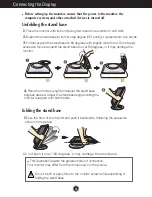
Page 4: ...ont of the monitor and push it backwards following the sequence shown in the picture 4 Place the monitor upright and adjust the stand base angle as desired Adjust the stand base angle holding the monitor head part with both hands Do not push it over 180 degrees It may damage the stand base 1 Place the monitor with its front facing downward on a cushion or soft cloth 2 Expand the stand base to its ...

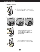
Page 5: ... downward as shown in the picture 3 After the cables are connected set the back cap into the groove of the upper section and reassemble by pushing upward 4 Insert the back cap along the bottom grooves on both sides holding the bottom 2 Connect the signal input cable and the power cord see next page ...

Page 6: ...Self Image Setting Function is executed automatically NOTE Self Image Setting Function This function provides the user with optimal display settings When the user connects the monitor for the first time this function automatically adjusts the display to optimal settings for individual input signals If you want to adjust the monitor while in use or wish to manually run this function once again push...

Page 7: ...enter or exit the On Screen Display Use this button to turn the display on or off This Indicator lights up blue when the display operates normally If the display is in DPM Energy Saving mode this indicator color changes to amber Power Button Power DPMS Indicator Use this button to enter a selection in the On Screen Display AUTO SELECT Button Control Function ...

Page 8: ... cannot be inadvertently changed Press and hold the MENU button for 5 seconds the message OSD LOCKED appears You can unlock the OSD controls at any time by pushing the MENU button for 5 seconds the message OSD UNLOCKED will appear OSD LOCKED UNLOCKED MENU Control Direct Access Function AUTO IMAGE ADJUSTMENT MENU B R I G H T N E S S 50 50 0 When adjusting your display settings always press the AUTO...

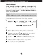
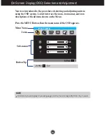
Page 9: ...able adjustments and selections you can make using the OSD To make adjustments in the On Screen Display follow these steps Press the MENU Button then the main menu of the OSD appears To access a control use the or Buttons When the icon you want becomes highlighted press the AUTO SELECT Button Use the Buttons to adjust the item to the desired level Accept the changes by pressing the AUTO SELECT But...

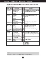
Page 10: ...justment and setting menus PRESET RED GREEN BLUE To adjust the position of the screen To restore the default settings To customize the color of the screen To customize the screen status for a user s operating environment To select or customize desired image settings To improve the clarity and stability of the screen BRIGHTNESS CONTRAST GAMMA H POSITION V POSITION CLOCK PHASE FACTORY RESET WHITE BA...

Page 11: ...g the OSD system Listed below are the icons icon names and icon descriptions of the all items shown on the Menu Press the MENU Button then the main menu of the OSD appears Menu Name Icons Sub menus P I C T U R E 50 50 0 MENU NOTE OSD On Screen Display menu languages on the monitor may differ from the manual MENU Exit Button Tip ...

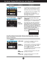
Page 12: ...whitish images and low gamma values display high contrast images MENU B R I G H T N E S S 50 50 0 PICTURE Select the screen color 6500K Slightly reddish white 9300K Slightly bluish white Set your own red color levels Set your own green color levels Set your own blue color levels P R E S E T 50 50 50 6500K 9300K MENU COLOR H POSITION V POSITION To move image left and right To move image up and down...

Page 13: ...output level of the video card in order to provide the optimal image Activate this function when white and black colors are present in the screen For example If this does not improve the screen image restore the factory default settings If necessary perform the white balance function again This function will be enabled only when the input signal is an analog signal F A C T O R Y R E S E T Y E S P ...

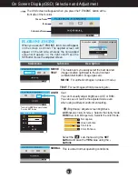
Page 14: ... screen will appear when you press the F ENGINE button at the front side of the monitor TEXT For text images Word processing etc Select the sub menu using the SET button and save the YES value using the buttons MOVIE For animation images in videos or movies This is under normal operating conditions This feature lets you easily select the best desired image condition optimized to the environment am...

Page 15: ...play is in power saving mode try moving the mouse or pressing any key on the keyboard to bring up the screen Make sure if the power is on Try to turn on the PC This message appears when the signal from the PC video card is out of horizontal or vertical frequency range of the display See the Specifications section of this manual and configure your display again This message appears when the signal ...

Page 16: ...ustyourdisplayimagetotheidealsetting Iftheresultsareunsatisfactory decreasethe verticalbarsorstripesusingthe CLOCKiconinthe on screen display Press the AUTO SELECTbuttontoautomatically adjustyourdisplayimagetotheidealsetting Iftheresultsareunsatisfactory decreasethe horizontalbarsusingthe PHASE icon in the on screen display CheckControlPanel Display Settingsand adjustthedisplaytotherecommendedreso...

Page 17: ...ver from the display driver CD or diskette that comes with your display Or you can also download the driver from our web site http www lge com Make sure to check if the video card supports Plug Play function USB function Check if the USB cable is correctly connected Check if the PC and OS are USB compliant For verification of USB support consult the manufacturer of each system USB function cannot ...

Page 18: ...end VESA 1280 x 1024 60Hz DDC 2B Normal 43W Stand by Suspend 2W DPMS Off 2W Full Up Position Folded Position Width 39 40cm 15 51inches 39 40cm 15 51inches Height 37 90cm 14 92inches 41 20cm 16 22inches Depth 23 20cm 9 13inches 12 70cm 5 00inches Net 4 5 kg 9 92 lbs Tilt 0 25 AC 100 240V 50 60Hz 1 0A Operating Conditions Temperature 10 C to 35 C Humidity 10 to 80 non Condensing Storage Conditions T...

Page 19: ... x 480 800 x 600 800 x 600 832 x 624 1024 x 768 1024 x 768 1152 x 870 1152 x 900 1280 x 1024 1280 x 1024 31 469 31 468 31 469 37 500 37 879 46 875 49 725 48 363 60 023 68 681 61 805 63 981 79 976 70 70 60 75 60 75 75 60 75 75 65 60 75 VGA VGA VGA VESA VESA VESA MAC VESA VESA MAC VESA VESA VESA Indicator Normal Stand by Suspend DPMS Off blue amber amber LED Color MODE ...

Page 20: ...DC Data Analog Vertical Sync T M D S Data1 T M D S Data1 T M D S Data1 3 Shield T M D S Data3 T M D S Data3 5V Power Ground return for 5V H Sync and V Sync Pin Signal DVI D 16 17 18 19 20 21 22 23 24 Hot Plug Detect T M D S Data0 T M D S Data0 T M D S Data0 5 Shield T M D S Data5 T M D S Data5 T M D S Clock Shield T M D S Clock T M D S Clock T M D S Transition Minimized Differential Signaling DVI ...

Page 21: ... with two hands as shown in the picture 3 Separate the stand base using a screwdriver as shown in the picture 4 Install the VESA standrad wall mounting Kensington Security Slot optional Connected to a locking cable that can be purchased separately at most computer stores VESA wall mounting Connected to another object stand type and wall mounted type This monitor accepts a VESA compliant mounting i...

Page 22: ...hed it USB connection 1 Connect the upstream port of the display to the downstream port of the USB compliant PC or another hub using the USB cable Computer must have a USB port 2 Connect the USB compliant peripherals to the downstream ports of the display NOTE To activate the USB hub function the display must be connected to a USB compliant PC OS or another hub with the USB cable enclosed When con...

Page 23: ...power USB devices such as a video camera scanner etc LGE recommends connecting high power USB devices directly to the computer Rev 1 1 complied BUS powered hub 100mA for each MAX 12 Mbps full 1 5 Mbps low 1 Upstream port 2 Downstream ports USBstandard Downstreampowersupply Communicationspeed USBport USB Specifications ...

Page 24: ...Digitally yours ...
Reviews: