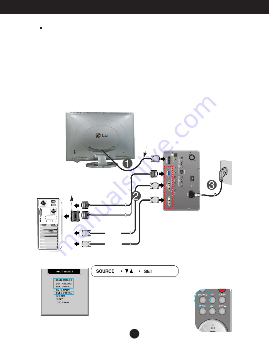
background image

A9

Press the 

SOURCE

button on the remote control to select an

input.

• DSUB ANALOG: 15-pin D-sub analog signal
• DVI-I ANALOG: DVI-I analog signal
• DVI-I DIGITAL: DVI-I digital signal
• DVI-D DIGITAL: DVI-D digital signal

Connecting the Display

Before setting up the monitor, ensure that the power to the monitor, the
computer system, and other attached devices is turned off. 

Using the Computer

1.

Connect the P&D (Plug and Display) cable. When attached, tighten the

thumbscrews to secure the connection. 

2.

Connect the signal cable

(2-1)

When connecting D-SUB signal cable

(2-2)

When connecting DVI-I signal cabl

(2-3)

When connecting DVI-D signal cable

3. 

Connect the power cord into a proper power outlet that is easily accessible

and close to the display.

(2-1)

(2-2)

(2-3)

PC

MAC

Mac adapter

For Apple Macintosh use, a separate plug adapter is needed to 
change the 15 pin high density (3 row) D-sub VGA connector 
on the supplied cable to a 15 pin 2 row connector.

P&D cable

4.

Select an input signal.

Summary of Contents for Flat Panel Monitor

Page 1: ...loaded AC outlets and extension cords are dangerous So are frayed power cords and broken plugs They may result in a shock or fire hazard Call your service technician for replacement Do not Open the Display There are no user serviceable components inside There are Dangerous High Voltages inside even when the power is OFF Contact your dealer if the display is not operating properly To Avoid Personal...

Page 2: ...ing hard as this may scratch mar or damage the Active Matrix LCD permanently Do not press the LCD screen with your finger for a long time as this may cause some afterimages Some dot defects may appear as Red Green or Blue spots on the screen However this will have no impact or effect on the display performance If possible use the recommended resolution to obtain the best image quality for your LCD...

Page 3: ...luded with your monitor If any items are missing contact your dealer Media Station Remote control Batteries AAA x 2 CD Rom Cards Signal Cable DVI D 15 pin D Sub Power Cord RCA Cable or SCART Cable It varies from country region to country region S Video Cable Audio Cable USB Cable Display ...

Page 4: ... people concentrate their focus upon the central area of the screen they do not clearly recognize a nonlinear expansion of the image near the edges of the display Therefore a 4 3 image can fit into the wide screen fairly naturally However it should be noted that this function is useful for TV or motion pictures but not suitable for a PC environment such as computer graphics or word processing Slee...

Page 5: ...splay mode It is available to the PC analog signal input only MUTE Button To select mute on or off CH Buttons VCR Buttons These buttons are available for LG VCR remote controls only Refer to the Owner s Manual for your VCR Power Button Bright Window Button This function provides exceptionally adjustable contrast and brightness that can be applied to any specially sized section of the screen SLEEP ...

Page 6: ...GITAL HDTV YPbPr SOURCE SOURCE DVI D VIDEO S VIDEO DVD YPbPr HDTV YPbPr When the signal of SOURCE 1 is supplied to the main screen the sub screen receives the signal of SOURCE 2 only Conversely when the signal of SOURCE 2 is supplied to the main screen the sub screen only receives the signal of SOURCE 1 The positions of SOURCE 1 and SOURCE 2 can be transposed by selecting SWAP HDTV supports both P...

Page 7: ... in each direction of the front of the remote sensor Do not expose the sensor of remote control in the monitor to a strong light source such as direct sunlight or illumination If so may not be able to operate the monitor with the remote control Note Do not drop the remote control or handle it roughly Do not leave the remote control in extremely hot or humid conditions Do not expose the remote cont...

Page 8: ...ing DVI D signal cable AV Input ports DVD YPbPr Input ports 480i 576i HDTV YPbPr Input ports 720p 1080i Connect the power cord Power cut off switch of the monitor DVD YPbPr HDTV YPbPr Audio L R Input ports LINE OUT A terminal used to connect to the speaker including a built in amplifier Amp Make sure that the connecting terminal of the PC sound card is checked before connecting If the Audio Out of...

Page 9: ...the Computer 1 Connect the P D Plug and Display cable When attached tighten the thumbscrews to secure the connection 2 Connect the signal cable 2 1 When connecting D SUB signal cable 2 2 When connecting DVI I signal cabl 2 3 When connecting DVI D signal cable 3 Connect the power cord into a proper power outlet that is easily accessible and close to the display 2 1 2 2 2 3 PC MAC Macadapter ForAppl...

Page 10: ...A10 Connecting the Display Connecting the Speakers Optional Connect the audio cable ...

Page 11: ...the Display or Media station If you connect the S Video input port to external equipment you can have an improved definition image 2 Select an input signal Press the SOURCE button on the remote control to select an input S VIDEO S video VIDEO Composite video S Video cable RCA cable Red White Yellow When connecting the RCA cable SCART Cable Whenconnecting the SCARTcable ...

Page 12: ...ach audio video output jack of the DVD to the corresponding input port as shown on the Display or Media station 2 Select an input signal Press the SOURCE button on the remote control to select an input DVD YPbPr DVDcable Optional Audiocable Optional When connecting the DVD cable Whenconnecting the SCARTcable ...

Page 13: ...button on the remote control to select an input HDTV YPbPr Watching HDTV 720p 1080i HDTVcable Optional HDTV Set Top Optional Red Blue Green Audiocable Optional 1 Connect both HDTV cable Y Pb Pr and audio cable Audio L R to the Display or Media station jack and the Set top box jack ...

Page 14: ...S VIDEO S video VIDEO Composite video DVD YPbPr DVD Source Selection The sub screen is changed in the order shown below SMALL LARGE OFF The positions of SOURCE 1 and SOURCE 2 can be transposed by selecting SWAP on the remote control PIP Picture in Picture function The sub screen is changed in the order shown below SMALL MEDIUM LARGE OFF The positions of SOURCE 1 and SOURCE 2 can be transposed by s...

Page 15: ...ems in the On Screen Display MENU Button Use this button to enter or exit the On Screen Display Use this button to turn the display on or off This Indicator lights up blue when the display operates normally If the display is in DPM Energy Saving mode this indicator color changes to amber Power Button Power DPMS Indicator Use this button to enter a selection in the On Screen Display Remote Control ...

Page 16: ...the available adjustments and selections you can make using the OSD To make adjustments in the On Screen Display follow these steps Press the MENU Button then the main menu of the OSD appears To access a control use the or Buttons When the icon you want becomes highlighted press the SET Button Use the Buttons to adjust the item to the desired level Accept the changes by pressing the SET Button Exi...

Page 17: ...nu A D Reference PRESET 9300K 6500K R G B User Color To adjust the position of the screen To customize the color of the screen To customize the screen status for a user s operating environment To improve the clarity and stability of the screen Adjustable A Analog Input D Digital Input BRIGHTNESS CONTRAST V POSITION H POSITION AUTO CLOCK PHASE LANGUAGE IMAGE SIZE OSD POSITION TRANSPARENCY ZOOM To a...

Page 18: ...ustomize the screen status for a user s operating environment To improve the clarity and stability of the screen LANGUAGE IMAGE SIZE OSD POSITION TRANSPARENCY To adjust the audio function Using the VCR DVD HDTV Adjustable V VCR DVD H HDTV MUTE VOLUME BASS TREBLE BBE EFFECT SOUND To adjust the PIP POP BRIGHT WINDOW of the screen PIP MODE POP MODE BRIGHT WINDOW ...

Page 19: ...he screen CONTRAST To adjust the contrast of the screen To adjust the brightness and contrast of the screen USER 9300K 6500K RED GREEN BLUE Set your own color levels Select the screen color 9300K Slightly bluish white 6500K Slightly reddish white To customize the color of the screen OSD Adjust Description To adjust the screen when using the computer Vertical Position To move image up and down Hori...

Page 20: ...cus of the display This item allows you to remove any horizontal noise and clear or sharpen the image of characters AUTO CLOCK PHASE To improve the clarity and stability of the screen OSD Adjust Description To adjust the audio function OSD Adjust Description Used to select mute on means sound off and mute off means sound on To decrease or increase volume level To decrease or increase bass level To...

Page 21: ...To adjust position of the OSD window on the screen Press the button to display the submenu for OSD POSITION To adjust the transparency of the OSD menu screen To adjust horizontal and vertical image size simultaneously If you want to move the zooming point use the H V POSITION function in the sub menu However if the monitor turns off when zooming in and out the screen the monitor will be returned t...

Page 22: ...he screen To adjust the color to desired level To adjust the tint to desired level CONTRAST BRIGHTNESS SHARPNESS COLOR TINT To adjust the audio function OSD Adjust Description Used to select mute on means sound off and mute off means sound on To decrease or increase volume level To decrease or increase bass level To decrease or increase treble level To adjust th clearness and sharpness of the soun...

Page 23: ...age size of the screen FULL SPECTACLE 4 3 To adjust position of the OSD window on the screen Press the button to display the submenu for OSD POSITION To adjust the transparency of the OSD menu screen To customize the screen status for a user s operating environment OSD Adjust Description LANGUAGE IMAGESIZE OSD POSITION TRANSPARENCY ...

Page 24: ...he PIP Picture in Picture of the screen OSD Adjust Description PIPSOURCE PIP SIZE PIP POSITION PIPIMAGE CONTRAST Toadjustthecontrastofthescreen BRIGHTNESS Toadjustthebrightnessofthescreen SHARPNESS Toadjusttheclearnessofthescreen COLOR Toadjustthecolortodesiredlevel TINT Toadjustthetinttodesiredlevel To select an input signal for PIP To adjust the size of the PIP screen SMALL LARGE To adjust the p...

Page 25: ... the image of the POP screen Press the button to display the submenu for POP IMAGE Use the buttons to adjust the item to the desired level To turn the POP sound on off To switch the main screen and sub screen in POP mode POPSOURCE POP SIZE POPIMAGE POPSOUND POPSWAP Afterselecting ONin thePOPON OFFmenu thefollowingmenuitemscanbeadjusted PC VCR DVD HDTV To turn the PIP sound on off To switch the mai...

Page 26: ...e applied to any specially sized section of the screen After selecting ON in the BRIGHT WINDOW menu you can adjust the following menu items HPOSITION VPOSITION HSIZE VSIZE CONTRAST BRIGHTNESS To move image left and right To move image up and down To adjust image width To adjust image height To adjust the contrast of the BRIGHT WINDOW To adjust the brightness of the BRIGHT WINDOW PC VCR DVD HDTV ...

Page 27: ...ls at any time by pushing the MENU button and VOL button for 5 seconds the message CONTROLS UNLOCKED will appear Check and see if the power cord is connected properly to the power outlet Press the Power button Adjust the brightness and the contrast If the display is in power saving mode try moving the mouse or pressing any key on the keyboard to bring up the screen Make sure if the power is on Try...

Page 28: ...lly adjust your display image to the ideal setting If the results are unsatisfactory decrease the vertical bars or stripes using the CLOCK icon in the on screen display Press the AUTO button to automatically adjust your display image to the ideal setting If the results are unsatisfactory decrease the horizontal bars using the PHASE icon in the on screen display Check Control Panel Display Settings...

Page 29: ...e manufacturer of each system IMAGE SIZE function on OSD menu does not work Have you installed the display driver Have you installed the display driver Do you see an Unrecognized monitor Plug Play VESA DDC monitor found message Be sure to install the display driver from the display driver CD or diskette that comes with your display Or you can also download the driver from our web site http www lge...

Page 30: ...f the SOUND is ON in the PIP POP OSD menu Adjust the TREBLE to an appropriate level Adjust the BASS to an appropriate level Select the BBE EFFECT to an appropriate level Check the volume level No sound No sound in PIP POP mode Sound is too high pitched or too low piched Sound level is too low A30 Troubleshooting Audio function ...

Page 31: ...al DVI I connector Digital Analog Composite video S video HDTV DVD Input Form RGB Analog 0 7Vp p 75ohm Digital S VIDEO CVBS Y Pb Pr Y Cb Cr Max D SUB 1920x1200 60Hz 1600x1200 75Hz DVI I 1600x1200 60Hz DVI D 1280x1024 60Hz Recommend D SUB WUXGA 1920 x 1200 60Hz DVI I UXGA 1600x1200 60Hz DVI D SVGA 1280x1024 60Hz DDC 2B Display Input DC 18 5V 4 5A DC 5V 0 5A Media station Input AC 100 240V 50 60Hz 1...

Page 32: ...ndensing Storage Conditions Temperature 20 C to 60 C Humidity 5 to 95 non Condensing 0 20 Attached O Detached Specifications Dimensions Weight Environmental Conditions Tilt Range Tilt Stand VESA wall mounting Connected to another object stand type and wall mounted type This monitor accepts a VESA compliant mounting interface pad KensingtonSecuritySlot optional Connected to a locking cable that can...

Page 33: ...1 469 37 500 43 269 37 879 46 875 53 674 49 725 48 363 60 123 68 677 68 681 61 805 63 981 79 976 75 000 93 750 74 556 70 70 60 75 85 60 75 85 75 60 75 85 75 65 96 60 75 60 75 60 VGA VGA VGA VESA VESA VESA VESA VESA MAC VESA VESA VESA MAC VESA VESA VESA VESA VESA VESA HDTV mode Component Video Input YPbPr Display Modes Resolution Horizontal Freq kHz Vertical Freq Hz 1 2 3 4 5 720 x 483 1280 x 720 1...

Page 34: ...Ground return for 5V H Sync and V Sync Pin Signal 16 17 18 19 20 21 22 23 24 C1 C2 C3 C4 C5 Hot Plug Detect T M D S Data0 T M D S Data0 T M D S Data0 5 Shield T M D S Data5 T M D S Data5 T M D S Clock Shield T M D S Clock T M D S Clock Analog Red Analog Green Analog Blue Analog H Sync Analog Ground T M D S Transition Minimized Differential Signaling C1 C5 DVI I only DVI D DVI I Connector Normal St...

Page 35: ...ices to be attached it USB connection 1 Connect the upstream port of the display or media station to the downstream port of the USB compliant PC or another hub using the USB cable Computer must have a USB port 2 Connect the USB compliant peripherals to the downstream ports of the display NOTE To activate the USB hub function the display must be connected to a USB compliant PC OS or another hub wit...

Page 36: ...Universal Serial Bus Optional Rev 1 0 complied Self powered hub 500mA for each MAX 12 Mbps full 1 5 Mbps low 1 Upstream port 2 Downstream ports USBstandard Downstreampowersupply Communicationspeed USBport USB Specifications ...

Reviews: