3-6
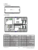
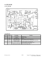
3. IP9009
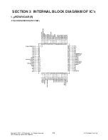
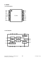
• PIN CONFIGURATION
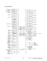
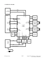
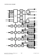
• BLOCK DIAGRAM
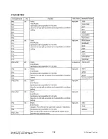
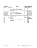
• PIN DESCRIPTION
No
SYMBOL
I/O
SYMBOL
1
FWD
I
Loading motor forward input
2
REV
I
Loading motor reverse input
3
CTL
I
Loading motor speed control
4
PS
I
Power save
5
IN1
I
CH1 input
6
IN2
I
CH2 input
7
SVCC
-
Signal power supply
8
PVCC1
-
Power supply 1
9
VOL-
O
Loading driver output(-)
10
VOL+
O
Loading driver )
11
VO2-
O
CH2 driver output(-)
12
VO2+
O
CH2 driver )
13
VO1-
O
CH1 driver output(-)
14
VO1+
O
CH1 driver )
No
SYMBOL
I/O
SYMBOL
15
VO4+
O
CH4 driver )
16
VO4-
O
CH4 driver output(-)
17
VO3+
O
CH3 driver )
18
VO3-
O
CH3 driver output(-)
19
GND
-
Ground
20
PVCC2
-
Power supply 2
21
MUTE
I
Mute
22
IN3
I
CH3 input
23
IN4
I
CH4 input
24
Vdet
I
Reset controller input
25
Reset
O
Reset controller output
26
REOadj
O
Adjustable regulator feedback
27
REBadj
O
Adjustable regulator control
28
BIAS
I
Bias
Copyright © 2007 LG Electronics. Inc. All right reserved.
Only for training and service purposes
LGE Internal Use Only

