


15
Specification
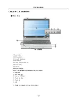
Chapter 3. System information
Ch3. System information
Processors
Intel Core Solo/Duo/Core Duo 2/ Celeron-m Processor
(L2 Cache Size: 1MB /2MB/4MB, FSB:
533MHz/667MHz)
The user must not replace or expand the CPU capacity arbitrarily. The CPU capacity differs depends on model type.
Main Memory
Maximum Size: Each slot is 1024MB and can be expanded to 2048MB.
SO DIMM Type for Memory Expansion: DDR2 SDRAM SO-DIMM (256MB, 512MB, 1024MB)
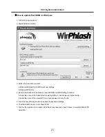
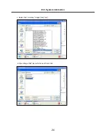
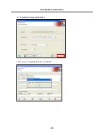
BIOS ROM
ROM: 4Mbit
Secondary Storage
2.5" Hard Disk Drive (SATA)
The hard disk capacity and the type depend on the notebook PC model.
Supports 4-in-1 ( SD / MMC / Memory Stick / Memory Stick Pro) Card
Optical Disk Drive
The specifications may differ by model type.
LCD
15.4" : WXGA(Resolution 1280 x 800) TFT Color LCD
Authentication for Anticopy Technology
U.S Patent Nos.4,631,603;4,577,216;4,819,908;4,907,093;5,315,448;and 6,516,132. Patent number of
Macrovision.
This product includes the technologies that are possessed by Macrovision and corresponding companies and
protected by the US Patent Law and other related laws. Use of all technologies subject to the copyrights must be
approved by Macrovision in advance. Otherwise, the technologies may only be used for internal display. Do not
disassemble or remodel the product.
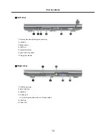
External I/O Interface
External VGA Monitor Port: 1
Microphone Input Port (Mic in): 1
Headset/Optical Output Port (S/PDIF): 1
Line-in Port: 1
External Battery Port: 1
USB 2.0 Ports: 4
4-in-1 (SD/MMC/Memory Stick/Memory Stick Pro) Card Slot: 1
RJ 11 (LAN) Port: 1
RJ 45 (LAN) Port: 1
Summary of Contents for F1
Page 1: ...0 Service Manual F1 LG Electronics ...
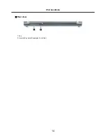
Page 15: ...14 Ch2 Locations Rear view 1 Fan 2 Security Key Hole Kensington Lock Hole ...
Page 56: ...55 Ch5 Removing and replacing a part ...
Page 58: ...57 3 Remove the Memory Module Ch5 Removing and replacing a part ...
Page 63: ...62 Ch5 Removing and replacing a part ...
Page 65: ...64 Ch5 Removing and replacing a part ...
Page 67: ...66 3 Remove the Keyboard Ch5 Removing and replacing a part ...
Page 69: ...68 3 Remove the Button Sub Board Ch5 Removing and replacing a part ...
Page 72: ...71 4 Remove the Display Module Ch5 Removing and replacing a part ...
Page 76: ...75 5 Remove the Main Board Ch5 Removing and replacing a part ...
Page 86: ...85 8 Disconnect the LCD Cable and the Inverter Connector Ch5 Removing and replacing a part ...
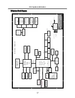
Page 92: ...91 NBATM NCVRB NCVRH NHDD1 NRUBS NSCR1 ...
Page 93: ...92 NODD1 NMEM1 NLAN1 NMDM1 NFAN1 ...
Page 94: ...93 NKBD1 NCPU1 NMCP1 NSPK1 NSPK1 NMLB1 NSUBU NSETR NCAPH NCABM NCAB3 NRUBR ...
Page 95: ...94 NCSEK NANTL NANTR NBRKR NSCR2 NCAB1 ...
Page 96: ...95 NSUBB NCSEB ...
Page 97: ...96 NBRKH NCSEF NHNGL NHNGR NSETR ...
Page 98: ...97 NSETF NCSER NLCD1 NNVE1 NCABN NCABL NPLTL ...
Page 99: ...98 NBRKL NBRKL NBRKL ...